|
|
|
[Sponsors] | ||||
 December 30, 2023, 13:10
|
|
#1 |
|
New Member
batuhan
Join Date: Dec 2023
Posts: 5
Rep Power: 3  |
Hello everyone,
I am new at SU2 and am trying to investigate the behavior of RAE 2822 at M=0,8 and 1,3 with different AoA(I am using o-mesh). However, my results do not come similar to my reference. I thought maybe my solver was wrong then tried it with M=0,66 and 0,729 but I took correct answers for those values. Also, I tried both initial options but still couldn't get the right results. So I couldn't find any solution can anybody help me? Thanks a lot My cfg file is like that; %%%%%%%%%%%%%%%%%%%%%%%%%%%%%%%%%%%%%%%%%%%%%%%%%% %%%%%%%%%%%%%%%%%%%%%%%%%%%%%% % % % SU2 configuration file % % Case description: Transonic simulation RAE2822 (RANS) % % Author: Francisco Palacios % % Institution: Stanford University % % Date: 5/15/2013 % % File Version 7.0.6 "Blackbird" % % % %%%%%%%%%%%%%%%%%%%%%%%%%%%%%%%%%%%%%%%%%%%%%%%%%% %%%%%%%%%%%%%%%%%%%%%%%%%%%%%% % ------------- DIRECT, ADJOINT, AND LINEARIZED PROBLEM DEFINITION ------------% % % Physical governing equations (EULER, NAVIER_STOKES, % WAVE_EQUATION, HEAT_EQUATION, FEM_ELASTICITY, % POISSON_EQUATION) SOLVER= RANS % % Specify turbulent model (NONE, SA, SA_NEG, SST) KIND_TURB_MODEL= SST % % Init option to choose between Reynolds (default) or thermodynamics quantities % for initializing the solution (REYNOLDS, TD_CONDITIONS) INIT_OPTION= TD_CONDITIONS % Mathematical problem (DIRECT, CONTINUOUS_ADJOINT) MATH_PROBLEM= DIRECT % % Restart solution (NO, YES) RESTART_SOL= NO % -------------------- COMPRESSIBLE FREE-STREAM DEFINITION --------------------% % % Mach number (non-dimensional, based on the free-stream values) MACH_NUMBER=0.8 % % Angle of attack (degrees, only for compressible flows) AOA=5.00 % % Free-stream temperature (288.15 K by default) FREESTREAM_TEMPERATURE= 298.15 % % Reynolds number (non-dimensional, based on the free-stream values) REYNOLDS_NUMBER= 17740149.26987561 % Free-stream density (1.2886 Kg/m^3, 0.0025 slug/ft^3 by default) FREESTREAM_DENSITY= 1.225 % Free-stream viscosity (1.853E-5 N s/m^2, 3.87E-7 lbf s/ft^2 by default) FREESTREAM_VISCOSITY= 1.52E-5 % % Reynolds length (1 m by default) REYNOLDS_LENGTH= 1.0 % ---------------------- REFERENCE VALUE DEFINITION ---------------------------% % % Reference origin for moment computation REF_ORIGIN_MOMENT_X = 0.25 REF_ORIGIN_MOMENT_Y = 0.00 REF_ORIGIN_MOMENT_Z = 0.00 % % Reference length for pitching, rolling, and yawing non-dimensional moment REF_LENGTH= 1.0 % % Reference area for force coefficients (0 implies automatic calculation) REF_AREA= 1.0 REF_DIMENSIONALIZATION= FREESTREAM_VEL_EQ_ONE % -------------------- BOUNDARY CONDITION DEFINITION --------------------------% % % Navier-Stokes wall boundary marker(s) (NONE = no marker) MARKER_HEATFLUX= ( airfoil, 0.0 ) % % Farfield boundary marker(s) (NONE = no marker) MARKER_FAR= ( farfield) % % Marker(s) of the surface to be plotted or designed MARKER_PLOTTING= ( airfoil) % % Marker(s) of the surface where the functional (Cd, Cl, etc.) will be evaluated MARKER_MONITORING= ( airfoil ) % ------------- COMMON PARAMETERS DEFINING THE NUMERICAL METHOD ---------------% % % Numerical method for spatial gradients (GREEN_GAUSS, WEIGHTED_LEAST_SQUARES) NUM_METHOD_GRAD= WEIGHTED_LEAST_SQUARES NUM_METHOD_GRAD_RECON= LEAST_SQUARES % % Courant-Friedrichs-Lewy condition of the finest grid CFL_NUMBER= 10 % % Adaptive CFL number (NO, YES) CFL_ADAPT= NO % % Parameters of the adaptive CFL number (factor down, factor up, CFL min value, % CFL max value ) CFL_ADAPT_PARAM= ( 0.01, 2, 0.0001, 1000 ) % % Number of total iterations ITER= 99999 % % Linear solver for the implicit formulation (BCGSTAB, FGMRES) LINEAR_SOLVER= FGMRES % % Min error of the linear solver for the implicit formulation LINEAR_SOLVER_ERROR= 1E-4 % % Max number of iterations of the linear solver for the implicit formulation LINEAR_SOLVER_ITER= 5 % -------------------------- MULTIGRID PARAMETERS -----------------------------% % % Multi-Grid Levels (0 = no multi-grid) MGLEVEL= 0 % % Multi-grid cycle (V_CYCLE, W_CYCLE, FULLMG_CYCLE) MGCYCLE= W_CYCLE % % Multi-grid pre-smoothing level MG_PRE_SMOOTH= ( 1, 2, 3, 3 ) % % Multi-grid post-smoothing level MG_POST_SMOOTH= ( 0, 0, 0, 0 ) % % Jacobi implicit smoothing of the correction MG_CORRECTION_SMOOTH= ( 0, 0, 0, 0 ) % % Damping factor for the residual restriction MG_DAMP_RESTRICTION= 0.95 % % Damping factor for the correction prolongation MG_DAMP_PROLONGATION= 0.95 % -------------------- FLOW NUMERICAL METHOD DEFINITION -----------------------% % % Convective numerical method (JST, LAX-FRIEDRICH, CUSP, ROE, AUSM, HLLC, % TURKEL_PREC, MSW) CONV_NUM_METHOD_FLOW= ROE % % Monotonic Upwind Scheme for Conservation Laws (TVD) in the flow equations. % Required for 2nd order upwind schemes (NO, YES) MUSCL_FLOW= YES % % Slope limiter (VENKATAKRISHNAN, MINMOD) SLOPE_LIMITER_FLOW= VENKATAKRISHNAN % % Coefficient for the limiter (smooth regions) VENKAT_LIMITER_COEFF= 0.05 % % 2nd and 4th order artificial dissipation coefficients JST_SENSOR_COEFF= ( 0.5, 0.02 ) % % Time discretization (RUNGE-KUTTA_EXPLICIT, EULER_IMPLICIT, EULER_EXPLICIT) TIME_DISCRE_FLOW= EULER_IMPLICIT % -------------------- TURBULENT NUMERICAL METHOD DEFINITION ------------------% % % Convective numerical method (SCALAR_UPWIND) CONV_NUM_METHOD_TURB= SCALAR_UPWIND % % Monotonic Upwind Scheme for Conservation Laws (TVD) in the turbulence equations. % Required for 2nd order upwind schemes (NO, YES) MUSCL_TURB= NO % % Time discretization (EULER_IMPLICIT) TIME_DISCRE_TURB= EULER_IMPLICIT % --------------------------- CONVERGENCE PARAMETERS --------------------------% % % Convergence criteria (CAUCHY, RESIDUAL) % CONV_FIELD= LIFT % % % Min value of the residual (log10 of the residual) CONV_RESIDUAL_MINVAL= -9 % % Start convergence criteria at iteration number CONV_STARTITER= 10 % % Number of elements to apply the criteria CONV_CAUCHY_ELEMS= 100 % % Epsilon to control the series convergence CONV_CAUCHY_EPS= 1E-6 % % ------------------------- INPUT/OUTPUT INFORMATION --------------------------% % % Mesh input file MESH_FILENAME= o_fine_f30_m08.su2 % % Mesh input file format (SU2, CGNS, NETCDF_ASCII) MESH_FORMAT= SU2 % % Mesh output file % % Restart flow input file SOLUTION_FILENAME= restart_flow.dat % % Restart adjoint input file SOLUTION_ADJ_FILENAME= solution_adj.dat % % Output file format (PARAVIEW, TECPLOT, STL) TABULAR_FORMAT= CSV % % Output file convergence history (w/o extension) CONV_FILENAME= history % % Output file restart flow RESTART_FILENAME= restart_flow.dat % % Output file restart adjoint RESTART_ADJ_FILENAME= restart_adj.dat % % Output file flow (w/o extension) variables VOLUME_FILENAME= flow % % Output file adjoint (w/o extension) variables VOLUME_ADJ_FILENAME= adjoint % % Output objective function gradient (using continuous adjoint) GRAD_OBJFUNC_FILENAME= of_grad.dat % % Output file surface flow coefficient (w/o extension) SURFACE_FILENAME= surface_flow % % Output file surface adjoint coefficient (w/o extension) SURFACE_ADJ_FILENAME= surface_adjoint % % Writing solution file frequency OUTPUT_WRT_FREQ= 100 % % Writing convergence history frequency SCREEN_WRT_FREQ_INNER= 1 % % Screen output fields SCREEN_OUTPUT= (INNER_ITER, RMS_DENSITY, RMS_NU_TILDE, LIFT, DRAG, LINSOL_ITER, AVG_CFL ) VOLUME_OUTPUT= (COORDINATES, SOLUTION, PRIMITIVE, RESIDUAL) HISTORY_OUTPUT= (INNER_ITER, RMS_DENSITY, DRAG, LIFT, NNER_ITER, RMS_DENSITY, RMS_MOMENTUM-X,RMS_MOMENTUM-Y, RMS_ENERGY) |
|

|

|
|
|
December 31, 2023, 05:56
|
|
#2 |
|
Senior Member
bigfoot
Join Date: Dec 2011
Location: Netherlands
Posts: 676
Rep Power: 21 |
do you have a figure showing the results for the different mach numbers (with the comparison w. literature), together with a figure of the residual convergence?
|
|
|
|
|
|
|
January 2, 2024, 09:39
|
|
#3 | |
|
New Member
batuhan
Join Date: Dec 2023
Posts: 5
Rep Power: 3 |
Quote:
|
||
|
|
|
||
|
January 2, 2024, 16:23
|
|
#4 |
|
Senior Member
bigfoot
Join Date: Dec 2011
Location: Netherlands
Posts: 676
Rep Power: 21 |
Below is a comparison between the pressure coefficients from the Testcases configuration file (SST) and the experimental data from the nasa website (Ma=0.73)(https://www.grc.nasa.gov/WWW/wind/va...af/raetaf.html)
The difference in CL is less than 2%. So when your cases are all converged, then my best guess is that the testcase you are comparing to does not correspond to the testcase that you are simulating. 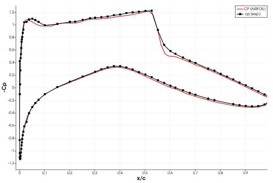
|
|
|
|
|
|
|
January 2, 2024, 17:49
|
|
#5 |
|
Senior Member
bigfoot
Join Date: Dec 2011
Location: Netherlands
Posts: 676
Rep Power: 21 |
BTW note that most RANS models cannot predict stall, so you will not be able to accurately predict the flow conditions for angles of attack higher than 6 degrees or so. I think stall happens at aoa=8-10 for the RAE 2822.
|
|
|
|
|
|
|
January 3, 2024, 09:50
|
|
#6 | |
|
New Member
batuhan
Join Date: Dec 2023
Posts: 5
Rep Power: 3 |
Quote:
|
||
|
|
|
||
|
January 3, 2024, 13:21
|
|
#7 |
|
Senior Member
bigfoot
Join Date: Dec 2011
Location: Netherlands
Posts: 676
Rep Power: 21 |
I think you should not draw any conclusions from a comparison of your results with numerical simulations that were 1. done with another code, 2. done with another turbulence model, 3. done without a grid convergence study, 4. done without verification with experiments.
For all we know, your results are correct and the paper of Kumar is wrong. I think it is better to (first) compare your setup with known measurements from the literature, like https://www.grc.nasa.gov/www/wind/va...af/raetaf.html https://www.sto.nato.int/publication...ARD-AR-138.pdf Even if this validation is successful, it will be difficult to say anything about higher mach and higher angle of attack without an experiment to compare to. |
|
|
|
|
|
|
January 4, 2024, 08:37
|
|
#8 | |
|
New Member
batuhan
Join Date: Dec 2023
Posts: 5
Rep Power: 3 |
Quote:
|
||
|
|
|
||
 |
|
|
 Similar Threads
|
||||
| Thread | Thread Starter | Forum | Replies | Last Post |
| Rae 2822 | bharatiaero | Main CFD Forum | 5 | December 31, 2022 14:15 |
| transonic RAE 2822 Airfoil grid..help | Michel | Main CFD Forum | 6 | April 14, 2019 09:45 |
| Rae 2822 | ZakBristol | Main CFD Forum | 1 | February 22, 2017 18:20 |
| Shockwave location RAE 2822 | mm391 | ANSYS | 0 | March 11, 2014 17:29 |
| 2D c-mesh around RAE 2822 profile | CFD student | Main CFD Forum | 2 | September 7, 2004 12:03 |
 5Likes

 Linear Mode


