|
|
|
[Sponsors] | ||||
 April 22, 2016, 12:33
|
|
#1 |
|
New Member
Tommaso Pascon
Join Date: Mar 2016
Posts: 18
Rep Power: 10  |
Hi everyone!
I'm doing some benchmark on flows past cylinder (square and circular) at high Reynolds numbers. I have already simulated the square 2D cylinder using the K-W SST model with great results. I have now to do the case with B/D = 5 where B is the along flow dimension. I have some doubts on what to use as reference. Usually i fix the velocity of the inlet at 1 m/s and modifiy nu to get the desired Reynolds number. But in this case Should i use B or D to get nu? And also should i use lref as B or as D for the calculation of the drag, lift and momentum coefficient? I think i could just use everything like the square cylinder case and just change the mesh ( basically that would mean taking D as reference)..but yeah i'm not sure about it; if someone can help me i would really appreciate it! Thanks! |
|

|

|
|
|
April 26, 2016, 13:04
|
|
#2 |
|
New Member
Tommaso Pascon
Join Date: Mar 2016
Posts: 18
Rep Power: 10 |
Ok so I found some papers of other CFD simulation and they take the breath of the rectangular cylinder as reference. Now i have another question. I did a complete structured grid mesh and a hybrid mesh (boundary layer with structured elements and everything else as unstructured) and i ran the same case with both the meshes. I get good results for both (B/D = 5 - Cd = 1.12 for the structured and 1.11 for hybrid) but i see that with the structured one i can use a bigger dt in pimpleFoam with the same Courant Number (0.5), so the simulation end faster than in the oder case. How can be such a big difference (dt = 0.005 and dt = 0.0001)?
Maybe because the mesh is more aligned with the flow in the first case? |
|
|
|
|
|
|
April 26, 2016, 14:21
|
|
#3 |
|
Senior Member
Join Date: Jun 2012
Location: Germany, Bochum
Posts: 230
Rep Power: 16 |
The Courant number is just a function of the velocity and the cell size (besides dt) . Since the flow field will be quite similar in both simulation I guess that in the areas of the highest velocities the cell size in flow direction is quite different in your case.
|
|
|
|
|
|
|
May 6, 2016, 12:46
|
|
#4 |
|
New Member
Tommaso Pascon
Join Date: Mar 2016
Posts: 18
Rep Power: 10 |
Hi again guys,
i need some help on this problem. In the past few days i run URANS 2D simulation of a air flow past rectangular cylinder (square and B/D = 5) using both K-W SST and Realizable K-Epsilon turn. models with wall function; since the flow is at high Reynold number (10^5) i cannot use EWT cause to get y+ = 1 the mesh should be too fine and the computation time too long. Anyway with that Reynolds number i got great results compared to what you can find in literature. My thesis supervisor now asked me to do the same analysis but with lower reynolds number (22000). I was pretty confident that i could get more good results but that was not the case. For the square cylinder i'm getting a Cd = 1.8 and a St =0.14 for both models while the reference values are 2.1 and 0.12. I really don't know what am i doing wrong. I know that for a rectangular cylinder the drag coefficient and Strouhal number should remain constant. I really need your help cause i'm pretty new to CFD and OpenFOAM (just 2 months) cause i'm a Civil Engineer Student and maybe i don't really now all the correct setting to use. For example i want to run the square cylinder case: Re = 22000; rho = 1.225 nu = 1.5e-5 (air) U = 0.165 m/s; D = B = 2 m; I = 2%; l = 0.07D = 0.14 m; k = 3/2*(UI)^2=1.63e-5; Omega at the inlet = (k^1.5)/(0.09*k*0.07*D) = 0.321; Omega at the wall = (60*nu)/(0.075*((y)^2)) = 36 with y the centroid of the height of the first cell - first cell height = 0.0365 so y = 0.5*0.0365; Max Courant number below 0.5 y+ min 1.3 and y+ max = between 30-40. Number of cells = 17771 I will post now my 0 and system files: U: PHP Code:
PHP Code:
PHP Code:
PHP Code:
PHP Code:
PHP Code:
PHP Code:
PHP Code:
Epsilon: (0.164*(k^1.5))/(0.07*D) = 1.34e-3; Basically i need to get Cd, Cl and Cm and check if the values of Cd and St match the literature ones. I am really spending a lot of time in this and i've plenty of more benchmark case to do (also on Reynolds = 10^6). This is just the first part in my master thesis and after this i should use what i've learned for a real case of a building but right now it seems to me something that will take me a lot of time only just for the benchmark. Please i would really be pleased if someone could check if what i've done is correct, and also give me some suggestion or tips or i don't know..but I am really interested in improving my cfd capabilities. Tell me if you need more files or settings i used for the simulation, i will be glad to upload them here. |
|
|
|
|
|
|
May 8, 2016, 09:00
|
|
#5 |
|
New Member
Tommaso Pascon
Join Date: Mar 2016
Posts: 18
Rep Power: 10 |
Hi guys,
i modified the fvScheme and fvSolution files following the suggestion of this pdf file:http://www.dicat.unige.it/guerrero/o...turbulence.pdf Here the mesh images (yPlusmax = 30-40):    And here the checkMesh output (i think everything is fine): Code:
/*---------------------------------------------------------------------------*\
| =========                 |                                                 |
| \\      /  F ield         | OpenFOAM: The Open Source CFD Toolbox           |
|  \\    /   O peration     | Version:  2.3.x                                 |
|   \\  /    A nd           | Web:      www.OpenFOAM.org                      |
|    \\/     M anipulation  |                                                 |
\*---------------------------------------------------------------------------*/
/*  Windows port by CFD support (www.cfdsupport.com) [based on Symscape]     *\
\*---------------------------------------------------------------------------*/
Build  : 2.3.x-9fde634ac4fb
Exec   : C:\OpenFOAM\cygwin64\opt\OpenFOAM\OpenFOAM-2.3.x\platforms\cygwin64mingw-w64DPOpt\bin\checkMesh.exe
Date   : May 08 2016
Time   : 12:37:02
Host   : "GRANDEPACCO"
PID    : 2028
Case   : C:/OpenFOAM/vecchia/run/rettangoli/104/KW
nProcs : 1
fileModificationChecking : Monitoring run-time modified files using timeStampMaster
allowSystemOperations : Disallowing user-supplied system call operations

// * * * * * * * * * * * * * * * * * * * * * * * * * * * * * * * * * * * * * //
Create time

Create polyMesh for time = 0

Time = 0

Mesh stats
    points:           48846
    internal points:  0
    faces:            96303
    internal faces:   47457
    cells:            23960
    faces per cell:   6
    boundary patches: 6
    point zones:      0
    face zones:       0
    cell zones:       0

Overall number of cells of each type:
    hexahedra:     23960
    prisms:        0
    wedges:        0
    pyramids:      0
    tet wedges:    0
    tetrahedra:    0
    polyhedra:     0

Checking topology...
    Boundary definition OK.
    Cell to face addressing OK.
    Point usage OK.
    Upper triangular ordering OK.
    Face vertices OK.
    Number of regions: 1 (OK).

Checking patch topology for multiply connected surfaces...
    Patch               Faces    Points   Surface topology
    inlet               120      242      ok (non-closed singly connected)
    outlet              120      242      ok (non-closed singly connected)
    top                 143      288      ok (non-closed singly connected)
    bottom              143      288      ok (non-closed singly connected)
    cylinder            400      800      ok (non-closed singly connected)
    sides               47920    48846    ok (non-closed singly connected)

Checking geometry...
    Overall domain bounding box (-20 -20 0) (50 20 1)
    Mesh (non-empty, non-wedge) directions (1 1 0)
    Mesh (non-empty) directions (1 1 0)
    All edges aligned with or perpendicular to non-empty directions.
    Boundary openness (1.8313e-018 5.7991e-017 7.01997e-018) OK.
    Max cell openness = 2.61296e-016 OK.
    Max aspect ratio = 23.1897 OK.
    Minimum face area = 0.000753279. Maximum face area = 7.74374.  Face area magnitudes OK.
    Min volume = 0.000753279. Max volume = 7.74374.  Total volume = 2796.  Cell volumes OK.
    Mesh non-orthogonality Max: 44.7121 average: 23.3794
    Non-orthogonality check OK.
    Face pyramids OK.
    Max skewness = 1.8416 OK.
    Coupled point location match (average 0) OK.

Mesh OK.

End
Code:
/*--------------------------------*- C++ -*----------------------------------*\
| =========                 |                                                 |
| \\      /  F ield         | OpenFOAM: The Open Source CFD Toolbox           |
|  \\    /   O peration     | Version:  2.3.x                                 |
|   \\  /    A nd           | Web:      www.OpenFOAM.org                      |
|    \\/     M anipulation  |                                                 |
\*---------------------------------------------------------------------------*/
FoamFile
{
    version     2.0;
    format      ascii;
    class       dictionary;
    location    "system";
    object      fvSchemes;
}
// * * * * * * * * * * * * * * * * * * * * * * * * * * * * * * * * * * * * * //

ddtSchemes
{
    default     CrankNicolson 0.5;
}

gradSchemes
{
    default         cellMDLimited Gauss linear 0.5;
    grad(p)         cellMDLimited Gauss linear 0.5;
    grad(U)         cellMDLimited Gauss linear 0.5;
}

divSchemes
{
    default         none;
    div(phi,U)      Gauss linearUpwind grad(U);
    div(phi,k)      Gauss linearUpwind default;
    div(phi,omega)  Gauss linearUpwind default;
    div((nuEff*dev(T(grad(U))))) Gauss linear;
}


laplacianSchemes
{
    default          Gauss linear limited 1.0;
}

interpolationSchemes
{
    default         linear;
    interpolate(U)  linear;
}

snGradSchemes
{
    default         limited 1.0;
}

fluxRequired
{
    default         no;
    p;
}

wallDist
{
    method meshWave;
}


// ************************************************************************* //
Code:
/*--------------------------------*- C++ -*----------------------------------*\
| =========                 |                                                 |
| \\      /  F ield         | OpenFOAM: The Open Source CFD Toolbox           |
|  \\    /   O peration     | Version:  2.1.x                                 |
|   \\  /    A nd           | Web:      www.OpenFOAM.org                      |
|    \\/     M anipulation  |                                                 |
\*---------------------------------------------------------------------------*/
FoamFile
{
    version     2.0;
    format      ascii;
    class       dictionary;
    location    "system";
    object      fvSolution;
}
// * * * * * * * * * * * * * * * * * * * * * * * * * * * * * * * * * * * * * //

solvers
{
    p
    {
        solver          PCG;
        preconditioner  DIC;
        tolerance       1e-06;
        relTol          0;
    }

    pFinal
    {
        solver          PCG;
        preconditioner  DIC;
        tolerance       1e-06;
        relTol          0;
    }

    U
    {
        solver          PBiCG;
        preconditioner  DILU;
        tolerance       1e-08;
        relTol          0;
    }

    k
    {
        solver          PBiCG;
        preconditioner  DILU;
        tolerance       1e-08;
        relTol          0;
    }

    omega
    {
        solver          PBiCG;
        preconditioner  DILU;
        tolerance       1e-08;
        relTol          0;
    }

    R
    {
        solver          PBiCG;
        preconditioner  DILU;
        tolerance       1e-08;
        relTol          0;
    }

    nuTilda
    {
        solver          PBiCG;
        preconditioner  DILU;
        tolerance       1e-08;
        relTol          0;
    }
}

relaxationFactors
{
    p           0.3;
    U           0.7;
    k           0.7;
    omega       0.7;
}

PISO
{
    nCorrectors     2;
    nNonOrthogonalCorrectors 3;
    pRefCell        0;
    pRefValue       0;
}

// ************************************************************************* //
With this settings I got: Cd = 2.17 (fine literature is 2.15) St = 0.84 (not good cause literature is 0.11-0.13). What might be wrong? The mesh (i don't think so cause the results are mesh independent)? I think the fvScheme might be the problem here. Is it normal that the solution change so much just changing the fvScheme? How can i get better solution of my strouhal number? Please help me guys, just give me some tips. I would really appreciate it. Thanks. |
|
|
|
|
|
|
May 8, 2016, 19:11
|
|
#6 |
|
New Member
Tommaso Pascon
Join Date: Mar 2016
Posts: 18
Rep Power: 10 |
Sorry i mean i get a Strouhal number of 0.084 instead of 0.11-0.12.
|
|
|
|
|
|
|
May 12, 2016, 12:29
|
|
#7 |
|
New Member
Tommaso Pascon
Join Date: Mar 2016
Posts: 18
Rep Power: 10 |
If someone is interested i managed to get good results deleting the relaxation factor in the fvSolution file because i was using pisofoam and it doesn't required them.
Anyway...i have a doubt: if I want to use the wall functions i saw that the y+ values should be between 30 and 300. But in OpenFoam if I run the yPlusRAS command which value should i take as reference...y+min, y+max or average? |
|
|
|
|
|
|
May 13, 2016, 01:13
|
|
#8 |
|
Senior Member
Mahdi Hosseinali
Join Date: Apr 2009
Location: NB, Canada
Posts: 273
Rep Power: 18 |
First thanks for sharing the solution of problems when you find it.
not sure which version of OF you are using because it's now yPlus (LES and RAS). Anyway, your min and max should be in the range. If you are going to resolve the boundary layer then strictly speaking your max should be less than 1, but there are cases that it may exceed 1 in places that are not of interest, then you should look at the areas that are important to you. I guess not the case for your geometry. Also schemes would have a big effect on the solution. for example limitedLinear (kinda central) is less diffusive than upwind, so it gets lower drag (if your drag is dominated by shear rather than pressure). |
|
|
|
|
|
|
May 13, 2016, 10:29
|
|
#9 |
|
New Member
Tommaso Pascon
Join Date: Mar 2016
Posts: 18
Rep Power: 10 |
I found very difficult to get all the y+ value around the wall between 30 and 300 because there will be some spots with velocity close to 0. And i remember i found a post here saying that the y+ value of reference was the y+ max not the other...but maybe i'm wrong.
And I know that k-w SST turbulence model uses scalable wall function ...but I was wondering if the same applies for the Realizable K-Epsilon model. |
|
|
|
|
|
|
May 13, 2016, 13:21
|
|
#10 |
|
New Member
Tommaso Pascon
Join Date: Mar 2016
Posts: 18
Rep Power: 10 |
I forgot to mention that i used this site to estimate the first cell height http://www.pointwise.com/yplus/
I got Ds = 0.049; but when i run the simulation with that value I have a range of y+ between 2 and 45 approximately. In the case of the rectangular cylinder should I try to get all the y+ (min and max) in the range of 30-300? i thin that is impossibile cause of the leading edges separation points particular of this geometry. Am I missing something? |
|
|
|
|
|
|
May 26, 2016, 14:37
|
|
#11 |
|
New Member
Alexis
Join Date: Apr 2016
Posts: 3
Rep Power: 10 |
Hello Tommaso!
First thanks for sharing your problem and solutions to the community! I am new to openFoam and CFD and I am willing to use to estimate drag coefficient on some complexe geometry that is relatively blunt (not streamlined). I am also trying to run a simple square cylinder case (and other simple geometry) to make sure I am getting good result but I am having a hard time. I don't want to hijack your thread and I am posting my case because I think it is very closely related and it I think it can encourage a good discussion. First I have questions concerning your High Reynold simulation: For what I understand (correct me if I am wrong), I think that the cylinder at high Reynolds is a blunt body and that the drag mostly comes from pressure drag and the wake. The resolution of the complete boundary layer (y+<1) without wall function may not be very usefull. The mesh of the wake however is important. Your mesh seems really fine for the high Reynold case with wall function and I wonder how you get y+ larger than 30. Moreover I wonder how you got good prediction because I am not. I am using steady state simulation (simplefoam) and my model is 3d (symmetry on sides) because I will need to use similar conditions for my real application. My drag is either too low, or not converging and it is sensitive to fvscheme and turbulence model. How did you choose your mesh size in the wake, what is the boundary layer mesh specs? How did you select your fvSchemes and fvSolution parameters? I tried to go to your link but it does not talk about fvschemes... Do you think you could post more info on your high Reynolds Validation? I will try to post my model too. For your Low-Reynold simulation I think that is your low-Reynolds drag has a good portion of viscous drag (not only pressure), you should get better prediction with a lower y+ and without wall function (never tried). How do you know that the k-w SST implementation in openFoam is scallable. I think I saw somewhere that the k-w SST was a high reynold model and that the low-Re version was not implemented in OF. Therefore k-w SST should always be used with wall functions. http://bugs.openfoam.org/view.php?id=835 Maybe this was updated Ihave no idea. It's weird that the fvscheme and fvsolution change you solution so much but maybe it is like Mahdi said and the diffusivity is affected. (more important in your low-Re case). Here is a description of one of my models. Fluid: air Openfoam 3.0.1 -Reynolds 100000 (speed 60m/s, square 25mmx25mm, nu=15e-6) -Meshed in snappyHexMesh because I will use it for my real application. Attention paid to y+ and wake refinement region. I try to maintain y+ above 30 and I want to use wall functions -Most of the other parameters are copied from the motorbike tutorial -Maybe there is something wrong about my settings fort this specific type of case... Image describing the model 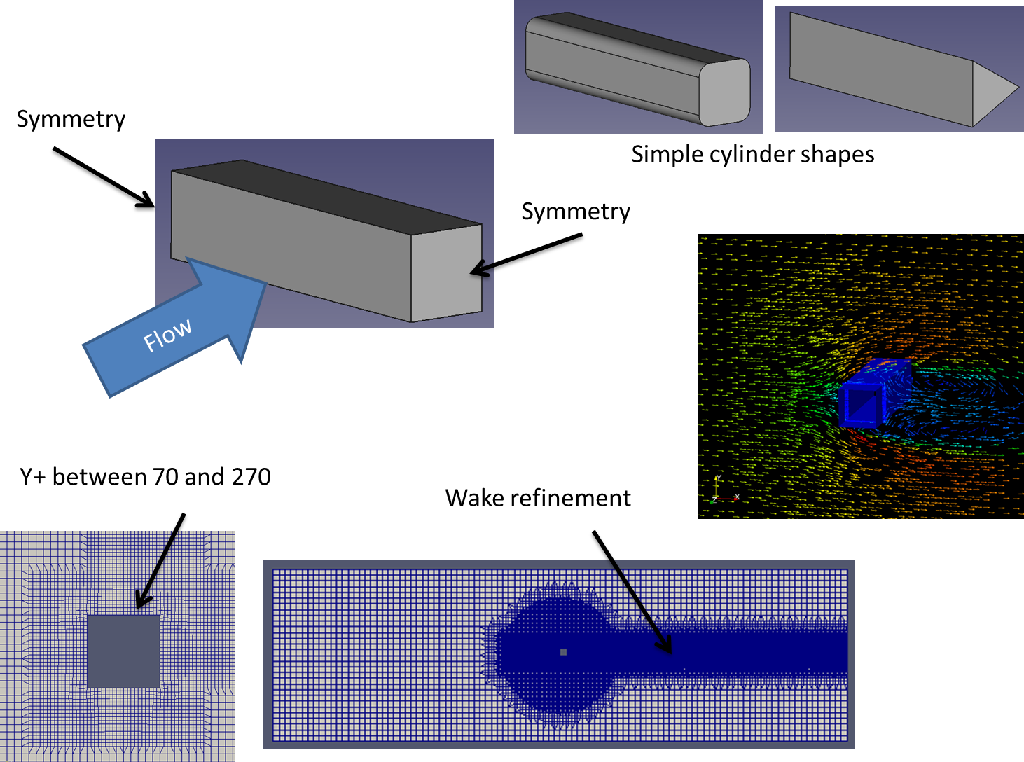 fvschemes Code:
ddtSchemes
{
    default         steadyState;
}

gradSchemes
{
    default         Gauss linear;
    grad(U)         cellLimited Gauss linear 1;
}

divSchemes
{
    default         none;
    div(phi,U)      bounded Gauss linearUpwindV grad(U);
    div(phi,k)      bounded Gauss upwind;
    div(phi,omega)  bounded Gauss upwind;
    div((nuEff*dev2(T(grad(U))))) Gauss linear;
}

laplacianSchemes
{
    default         Gauss linear corrected;
}

interpolationSchemes
{
    default         linear;
}

snGradSchemes
{
    default         corrected;
}

wallDist
{
    method meshWave;
}
Code:
solvers
{
    p
    {
        solver           GAMG;
        tolerance        1e-7;
        relTol           0.01;
        smoother         GaussSeidel;
        nPreSweeps       0;
        nPostSweeps      2;
        cacheAgglomeration on;
        agglomerator     faceAreaPair;
        nCellsInCoarsestLevel 10;
        mergeLevels      1;
    }

    Phi
    {
        $p;
    }

    U
    {
        solver           smoothSolver;
        smoother         GaussSeidel;
        tolerance        1e-8;
        relTol           0.1;
        nSweeps          1;
    }

    k
    {
        solver           smoothSolver;
        smoother         GaussSeidel;
        tolerance        1e-8;
        relTol           0.1;
        nSweeps          1;
    }

    omega
    {
        solver           smoothSolver;
        smoother         GaussSeidel;
        tolerance        1e-8;
        relTol           0.1;
        nSweeps          1;
    }
}

SIMPLE
{
    nNonOrthogonalCorrectors 0;
    consistent yes;
}

potentialFlow
{
    nNonOrthogonalCorrectors 10;
}

relaxationFactors
{
    equations
    {
        U               0.9;
        k               0.7;
        omega           0.7;
    }
}

cache
{
    grad(U);
}
Code:
#include        "include/initialConditions"

dimensions      [0 2 -2 0 0 0 0];

internalField   uniform $turbulentKE;

boundaryField
{
    //- Set patchGroups for constraint patches
    #includeEtc "caseDicts/setConstraintTypes"

    //- Define inlet conditions
	inlet
	{
		type  fixedValue;
		value $internalField;
	}

    outlet
    {
        type            inletOutlet;
        inletValue      $internalField;
        value           $internalField;
    }


    geometrie
    {
        type            kqRWallFunction;
        value           $internalField;
    }

	upperWall
	{
		type  fixedValue;
		value $internalField;
	}

	front
	{
		type symmetryPlane;
	}

	back
	{
		type symmetryPlane;
	}

	lowerWall
	{
		type  fixedValue;
		value $internalField;
	}
}
Code:
#include        "include/initialConditions"

dimensions      [0 0 -1 0 0 0 0];

internalField   uniform $turbulentOmega;

boundaryField
{
    //- Set patchGroups for constraint patches
    #includeEtc "caseDicts/setConstraintTypes"

	inlet
	{
		type  fixedValue;
		value $internalField;
	}

    outlet
    {
        type            inletOutlet;
        inletValue      $internalField;
        value           $internalField;
    }


    geometrie
    {
        type            omegaWallFunction;
        value           $internalField;
    }

	upperWall
	{
		type  fixedValue;
		value $internalField;
	}

	front
	{
		type symmetryPlane;
	}

	back
	{
		type symmetryPlane;
	}

	lowerWall
	{
		type  fixedValue;
		value $internalField;
	}
}
Code:
dimensions      [0 2 -1 0 0 0 0];

internalField   uniform 0;

boundaryField
{
    //- Set patchGroups for constraint patches
    #includeEtc "caseDicts/setConstraintTypes"


	front
	{
        type            symmetryPlane;
	}

	back
	{
        type            symmetryPlane;
	}

    inlet
    {
        type            calculated;
        value           uniform 0;
    }

    outlet
    {
        type            calculated;
        value           uniform 0;
    }

    lowerWall
    {
        type            calculated;
        value           uniform 0;
    }

    upperWall
    {
        type            calculated;
        value           uniform 0;
    }

    geometrie
    {
        type            nutkWallFunction;
        value           uniform 0;
    }
}
Code:
#include        "include/initialConditions"

dimensions      [0 2 -2 0 0 0 0];

internalField   uniform $pressure;

boundaryField
{
    //- Set patchGroups for constraint patches
    #includeEtc "caseDicts/setConstraintTypes"

    inlet
    {
        type            zeroGradient;
    }

    outlet
    {
        type            fixedValue;
        value           $internalField;
    }


    geometrie
    {
        type            zeroGradient;
    }

	upperWall
	{
        type            zeroGradient;
	}

	front
	{
		type symmetryPlane;
	}

	back
	{
		type symmetryPlane;
	}

	lowerWall
	{
        type            zeroGradient;
	}
}
Code:
#include        "include/initialConditions"

dimensions      [0 1 -1 0 0 0 0];

internalField   uniform $flowVelocity;

boundaryField
{
    //- Set patchGroups for constraint patches
    #includeEtc "caseDicts/setConstraintTypes"

	inlet
	{
		type  fixedValue;
		value $internalField;
	}

    outlet
    {
        type            inletOutlet;
        inletValue      uniform (0 0 0);
        value           $internalField;
    }


    geometrie
    {
        type            fixedValue;
        value           uniform (0 0 0);
    }

	upperWall
	{
		type  fixedValue;
		value $internalField;
	}

	front
	{
		type symmetryPlane;
	}

	back
	{
		type symmetryPlane;
	}

	lowerWall
	{
		type  fixedValue;
		value $internalField;
	}
}
Code:
flowVelocity (60 0 0); //20 original moto 0.15 donne Reyn 10000 pressure 0; turbulentKE 0.24; turbulentOmega 1.78; #inputMode merge |
|
|
|
|
|
|
May 26, 2016, 15:42
|
|
#12 |
|
New Member
Tommaso Pascon
Join Date: Mar 2016
Posts: 18
Rep Power: 10 |
Hi! I'm pretty new to cfd so i might tell you something wrong
 About the K-W SST model i read in some thread here that it can work as Low Reynolds model or as High Reynolds model. Depends on the refinement of the boundary layer and on the boundary condition used (wall function or not). About the scalable function i read that here:http://www.dicat.unige.it/guerrero/o...turbulence.pdf From what i understood with the scalable wall function you should get good results for any y+ (1< y+ < 300). Actually I would never go beyond 100 and the best should be to stay near 30 (but i'm not an expert). In some case with separated flow it is really difficult to keep the y+ value in between the range for every cell in the wall zone. I'm doing some other analysis on the square section (2D) with both RKE and K-W SST models with an y+ MAX =30, 60, 100. Right now for the RKE i got almost the same value for Cd and the Stoical number for the y+ max = 60 and 100. By tomorrow i think i'll be able to have all the analysis done. I would have expected RK-E to have a better behavior for y+Max = 100 cause the y+avg value is in between 30 and 40. An explanation might be that for pointed edge section the boundary layer separation happens because of the leading edges ; a different situation happens with circular cylinders where the wall function approach is not recommended at that high Re (but all RANS application in general). And also for the fvScheme search for the same professor of the presentation I posted the link before. In his page there is another presentation called tips and tricks where he talks about fvScheme and fvSoultion in general. He said that fvScheme is one of the most robust and accurate. But why are you running a steady state solution? At that Reynolds number the flow is turbulent. I used pisoFoam to study the unsteadiness of the flow. |
|
|
|
|
|
|
May 30, 2016, 12:31
|
|
#13 |
|
New Member
Alexis
Join Date: Apr 2016
Posts: 3
Rep Power: 10 |
Hello! Thanks for the fast reply!
The course from Guerrero do mention that scallable wall function can be used (only with the k-w family models, slide 50). However did you take a look at this link http://bugs.openfoam.org/view.php?id=835 Henry seems to be clear that a low-Re Version of k-w SST is not implemented and recommends the kkl omega. Maybe it has been corrected since its from 2013. I don't know how to verify this in the source code and I do not have acess to the original papers of the turbulence models cited in the source code. Just to be sure, what Boundary condition do you use when you don't want to use wall funciton? zeroGradient? I agree that it is hard to keep the y+ in the wanted range for this type of case. I am not sure if the max and min value are that important as long as most of the values are in the wanted range in the wanted zone. You can visualize the y+ value in Openfoam after using the yPlus command. I wonder how important it is however since most of the drag is pressure drag. Maybe solving the boundary layer is not so important since viscous drag is negligible? Maybe I am wrong and the point of transition is important for the shape of the wake and therefore solving the boundary layer would be good. I just don't know, to me, it seems like the transition is obvious on a blunt body at high reynolds. If anyone has another opinion on that you are welcome to share! :-) I am glad that your are also trying Realizable-keps. Did you manage to get similar drag than with the k-omega sst? On my side I did not. It change the result significantly. I guess you are using wall functions in that case? I am not sure I understand your explanation concerning separation at the leading edge. I thought that wall function and RANS were the thing to use when at high Reynolds? Maybe the cylinder is too complex and the separation needs to be resolved. I will try the fvschemes proposed by the course of Guerrero. I wish that was more explanation and documentation of this schemes elsewhere. Maybe it is just common CFD knowledge but unfortunatly I do not have a theoretical CFD formation. I am running steady state simply because I am not interested in transient response and I just want the drag coefficient in steady state. I think this practice is common even for turbulent drag analysis. I will try pisoFoam but I am not sure what it would change? I will continue working on my 3d cylinders and I hope to finally get guidelines to obtain consistently good results for various blunt geometry. I am not sure I remember if you managed to obtain good results at high Reynolds? If so what were you recommendations and guidelines? Do you think you could send me your code and geometry? I would love to take a look at it. Dis you do other geometry than a square? Fianl quick questions. How do you output the Strouhal number in Openfoam? What is the paper that you are comparing your results to? Thanks in advance again! |
|
|
|
|
|
|
February 14, 2017, 04:35
|
|
#14 | |
|
New Member
lynn Cheng
Join Date: Jan 2017
Posts: 3
Rep Power: 9 |
Quote:
May I ask you how you set the depth of the domain in Z direction? And did you got stable drag coefficient in your simulation? |
||
|
|
|
||
 |
|
|
 Similar Threads
|
||||
| Thread | Thread Starter | Forum | Replies | Last Post |
| Flow past a cylinder, Reynolds No: 100, Tracking strouhal Number. | Karan | FLUENT | 11 | November 14, 2016 05:49 |
| Flow past an oscillating cylinder (Strouhal number) | o_mars_2010 | Main CFD Forum | 8 | May 23, 2014 05:25 |
| Flow past rotating cylinder: Problem with ForeCoeffs | raf1111 | OpenFOAM | 1 | December 16, 2013 10:45 |
| Flow past rotating cylinder | sam.ho | OpenFOAM Running, Solving & CFD | 4 | October 10, 2013 08:49 |
| Drag coefficient of flow past cylinder vs time | pedroxramos | FLUENT | 0 | January 14, 2013 13:39 |
 2Likes

 Linear Mode


