|
|
|
[Sponsors] | ||||
 August 10, 2020, 06:45
|
|
#1 |
|
New Member
J.Q. Cong
Join Date: Feb 2019
Location: China
Posts: 4
Rep Power: 7  |
Hello,
I am doing the flutter simulation of NASA Rotor 67 based on the Energy method by ANSYS CFX, referring to the guidance of the ANSYS tutorial. ANSYS CFX: Blade Flutter Modelling using the Fourier Transformation Method https://www.youtube.com/watch?v=XBFjsdNaER0&t=105s Here I attach my CFD model and some main settings: Figure1.jpg Figure 1 Figure 2 Figure3.jpg Figure 3 Figure 4 I encountered two problems. 1. I set up the monitor of aerodynamic damping in CFX-Pre, as shown in Figure 5. Generally speaking, the aerodynamic damping will converge to a single value after about 10 vibration cycles, but for my calculation, the aerodynamic damping value is still fluctuating even after 20 cycles, as shown in Figure 6. Figure 5 Figure6.jpg Figure 6 2. Generally speaking, the closer to the stall point, the flutter is more prone to occur, thus the aerodynamic damping value will decrease. This conclusion is also drawn by many researchers. But the opposite trend is observed in my simulations. I have tried many methods to solve these two problems, including meshes, inlet and outlet boundary conditions, solution settings (numbers of Timesteps per Period, Max. Coeff. Loops), but all my efforts proved of little avail. I compared the steady-state results with experiments, including the characteristic curve and contours of relative Mach number. I also did the mesh independent test, it seems that there is nothing wrong with my mesh. I am trying to shorten the distance between the inlet and outlet to the blade, even less than the recommended one chord length, as shown in Figure 7. Generally speaking, the inlet and outlet are too close to the blade will get an inaccurate result, and there will be serious backflow in the outlet. But it is strange that the flutter calculation in this case does not have the above two problems. But I think the results in this case are not correct. I am not sure why shortening the inlet and outlet can solve these two problems, and I want to know how to solve the problem mentioned above. Figure7.jpg Figure 7 Does anyone know anything about this? All the best, Pangzi |
|

|

|
|
|
August 10, 2020, 10:24
|
|
#2 |
|
Senior Member
Join Date: Jun 2009
Posts: 1,880
Rep Power: 33 |
Not clear if you are trying to reproduce the results in the video, or running the simulation at a different operating point. I think the video is running near the design point, so be careful extrapolating those convergence characteristics to the stall region.
Have you used the "derived variables" feature in the ANSYS CFX SolverManager? You may be able to compute a moving average of the monitor point, or a moving "difference from the mean" that will show how much variation you have every timestep. On a separate note, are you getting accurate (time step independent) results at 60 timesteps per period away from the design point? Hope the above helps,
__________________
Note: I do not answer CFD questions by PM. CFD questions should be posted on the forum. |
|

|
|
|
|
August 10, 2020, 11:11
|
|
#3 |
|
New Member
J.Q. Cong
Join Date: Feb 2019
Location: China
Posts: 4
Rep Power: 7 |
Hi, Opaque
Thanks for your reply. I used the method in the video to perform my simulation. The case in the video is Rotor 37, and in my simulation is Rotor 67. The flutter simulation near the design point is taken as a demonstration in the video, while I want to get the flutter behaviors from choke point to near stall point. At near stall point, the convergence characteristic does deteriorate, so other work conditions, including the near design point, were also simulated, but the convergence did not improve. When setting the monitor of aerodynamic damping, the moving average of the aerodynamic damping is computed. Here I attach the screenshots of my settings and monitoring results: 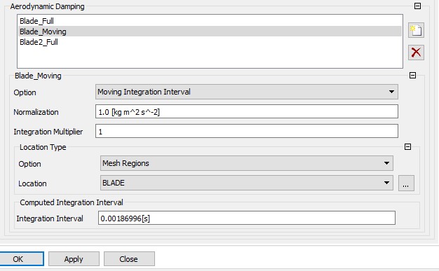 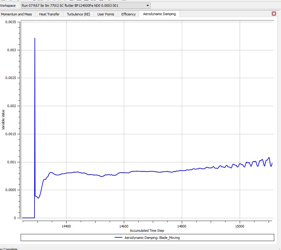 As for the time step, I tried 44, 60, 80, 100 steps per cycle, but the problem still exists. Best regards. |
|
|
|
|
|
|
August 10, 2020, 17:13
|
|
#4 |
|
Senior Member
Join Date: Jun 2009
Posts: 1,880
Rep Power: 33 |
Would you mind posting the convergence/residual plots for that specific case?
Rotor67 is not a "walk in the park" simulation near stall, or even at the design point. The mesh quality for that rotor is very important. I may be able to suggest other steps after looking at the residual plots.
__________________
Note: I do not answer CFD questions by PM. CFD questions should be posted on the forum. |
|
|
|
|
|
|
August 10, 2020, 22:26
|
|
#5 | |
|
New Member
J.Q. Cong
Join Date: Feb 2019
Location: China
Posts: 4
Rep Power: 7 |
Quote:
Both figures below are the residual plots. The first picture shows the residual plot of the whole history, the second one shows only the flutter simulation part. You can find that the second picture is last part of the first one from the abscissa axis. 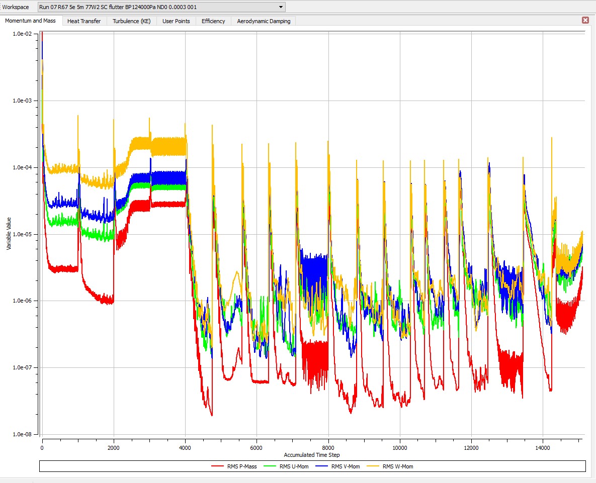  Best regards. |
||
|
|
|
||
|
August 11, 2020, 09:22
|
|
#6 |
|
Senior Member
Join Date: Jun 2009
Posts: 1,880
Rep Power: 33 |
Missing attachments?
__________________
Note: I do not answer CFD questions by PM. CFD questions should be posted on the forum. |
|
|
|
|
|
|
August 11, 2020, 09:38
|
|
#7 | |
|
New Member
J.Q. Cong
Join Date: Feb 2019
Location: China
Posts: 4
Rep Power: 7 |
Quote:
I have uploaded the attachment, everything is normal from my side. I can see the screenshot I attached. I will upload again below:  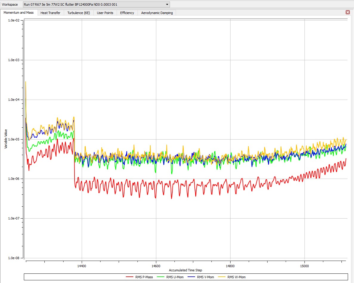 Or you can see the picture from the link below: https://sm.ms/image/HwdN9Z5GSbiU6Tr Best regards. |
||
|
|
|
||
 |
| Tags |
| aerodynamic damping, energy method, flutter, nasa rotor 67 |
|
|
 Similar Threads
|
||||
| Thread | Thread Starter | Forum | Replies | Last Post |
| Problem with restart in FSI unsteady simulation | david_mocholi | SU2 | 1 | June 24, 2023 07:06 |
| Specifying BC for LES simulation of pollutant dispersion problem in environment | jzuzul | OpenFOAM Running, Solving & CFD | 8 | June 21, 2018 08:21 |
| Problem with wall surface reaction simulation in Fluent | suren1992 | CFD Freelancers | 1 | June 7, 2018 05:14 |
| mpi run problem signal 11 (segmentation fault) FGM simulation | Fedindras | CONVERGE | 1 | October 26, 2017 17:05 |
| Large-scale simulation problem | Purushothama | Main CFD Forum | 0 | November 7, 2010 21:12 |
 1Likes

 Linear Mode


