 |
|
|
[Sponsors] | |||||
|
|
|
#1 |
|
New Member
Juan
Join Date: Jul 2009
Posts: 25
Rep Power: 17  |
Hello everybody, I have to import a solid piece from Solidworks to Icem cfd, There is any way to import directly?
I know that I have to convert the piece to igs or step, What is the best format? igs or step? When I choose step, in ICEM CFD---> Import Geometry--->IGS/STEP I look for the file. Before, this window appears: Import Geometry From Step or Iges Tetin file: the file´s name Use Version 5.1 Step Translator: Should I select it?? Create part name from STEP/IGES file: I can´t select this option Merge geometry files after conversion: I can´t select this option Ignore units: Use healing: I don´t select any option and click apply, the geometry appears without mistakes (I think), am I doing a good conversion? Thank you for your opinions. |
|
|
|

|
|
|
|
|
#2 |
|
Senior Member
Simon Pereira
Join Date: Mar 2009
Location: Ann Arbor, MI
Posts: 2,663
Blog Entries: 1
Rep Power: 47   |
There is a direct reader for Solidworks (costs extra), similar to the direct readers for Pro/E, UG, etc.
If you must stick with a neutral geometry format, then IGES is the worst and STEP is the second worst. Formats like ACIS (SAT) are much better (cleaner, more parametric, etc.) and still free to read in ICEM CFD. Most users should just go with the defaults. The other options are for a small percentage of users. If your import goes badly, tech support may suggest some of those options. If an option can't be selected, it is because it is not relevant based on your other settings. If your model looks fine, it probably is fine (even though IGES is the WORST  ). ).
|
|
|
|

|
|
|
|
|
#3 |
|
New Member
Join Date: Nov 2009
Posts: 14
Rep Power: 17  |
Hii I too am facing problems in importing from SolidWorks. I created my geometry in SolidWorks 2009, however when I tried to import it ICEM CFD told me that it could only do so for versions till 2007.
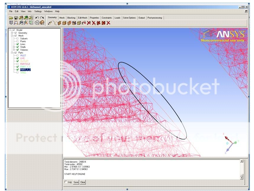
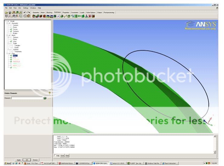
I also came to know that SolidWorks 2009 is supported in Ansys Workbench but not in ICEM CFD. So is there any work around by which I can import the geometry into Ansys Workbench and then send it to ICEM CFD? I did try to save my file in various other formats, but everytime I tried to do so, the geometry edges were not properly imported which resulted in distorted mesh generation. Could you tell me what version of Pro E is supported. I have Pro E wildfire 4.0 installed on my work computer. these are the images from ICEM CFD, and Solidworks. As you can see the geometry imported into ICEM CFD has miss matching surfaces even though the surfaces match perfectly in SolidWorks 2009   
|
|
|
|

|
|
|
|
|
#4 |
|
Senior Member
Simon Pereira
Join Date: Mar 2009
Location: Ann Arbor, MI
Posts: 2,663
Blog Entries: 1
Rep Power: 47   |
Sure...
If you have workbench installed on your machine and the version is the same as ICEM CFD... In ICEM CFD click on File => Workbench Readers. Browse to select your SW2009 file. Apply. It uses the workbench reader in the background but the translation goes directly into ICEM CFD. Alternativly, you could open the file in DesignModeler (or ANSYS Meshing or ANSYS Simulation) do what ever editing you want and then save it. Then go to ICEM CFD => File => Worbench readers and click on the saved workbench project or its sub file and import the model that way. |
|
|
|

|
|
|
|
|
#5 |
|
New Member
Join Date: Nov 2009
Posts: 14
Rep Power: 17  |
Actually I figured out the reason now...the reason that was happening was not related to solidworks import, but rather due to the tolerance. The default triangulation tolerance is set to .01, while my parts themselves have dimensions of the order of 10e-6 m
|
|
|
|

|
|
|
|
|
#6 |
|
Member
|
one question.. im working with solidworks to and cfx-mesh, and when i import the cad model to cfx mesh i convert the solidworks file cad, to .x_t (parasolid type), this its a good format for cfd?
thnks very much |
|
|
|

|
|
|
|
|
#7 |
|
Senior Member
Simon Pereira
Join Date: Mar 2009
Location: Ann Arbor, MI
Posts: 2,663
Blog Entries: 1
Rep Power: 47   |
AdidaKK,
Yes, Parasolid is good, ACIS is good, DXF is pretty good. IGES and Step are the worst. But true CAD (such as with the SolidWorks Direct interface, or direct translation from Pro/E, UG, Catia, etc.) is definitely the best. Back to Parasolid, DX it's self has a Parasolid kernel... So if you don't have access to a true CAD interface, Parasolid is a pretty good choice. |
|
|
|

|
|
|
|
|
#8 |
|
Member
|
thanks very veeeery much =), im using parasolid.
best regards |
|
|
|

|
|
|
|
|
#9 | |
|
Senior Member
Jie
Join Date: Jan 2010
Location: Australia
Posts: 134
Rep Power: 16  |
Quote:
I came across some thing very similar to yours. Hope you can give me some hints. (1) I tired to load a .step file to icemcfd and it asks for a .tin file. Otherwise, I can not load the .step file into icemcfd. Is the .tin file necessary? (2) My work around is to convert the .step to a .stl file and load the .stl file into icemcfd. However, the got face miss match like yours when I mesh the geometry (very irregular mesh elements along the curves, like your 2nd pic). You said your work around it is reduce the default triangulation tolerance. Where can I find this? Thank you very much. |
||
|
|

|
||
|
|
|
#10 |
|
Senior Member
Simon Pereira
Join Date: Mar 2009
Location: Ann Arbor, MI
Posts: 2,663
Blog Entries: 1
Rep Power: 47   |
JieJie...
The *.tin file is the ICEM CFD native geometry format. If you are bringing in a *.step file, you should "Import", not "open". This will convert your file into a *.tin. You shouldn't go from bspline or nurb geometry (surfaces) to faceted unless you have a really good reason (like you IGES file would have been 2 GIGs and the STL is much smaller). Going to a faceted format is a loss in fidelity... However, as I noted earlier... IGES and STEP are the worst of the formats, so if you have any better options... Tri tolerance is under Settings => Model.
__________________
----------------------------------------- Please help guide development at ANSYS by filling in these surveys Public ANSYS ICEM CFD Users Survey This second one is more general (Gambit, TGrid and ANSYS Meshing users welcome)... CFD Online Users Survey |
|
|
|

|
|
|
|
|
#11 |
|
New Member
Join Date: Jan 2012
Location: China
Posts: 1
Rep Power: 0  |
Help so much.Thanks,PSYMN.
|
|
|
|

|
|
|
|
|
#12 |
|
New Member
Simone Di Giorgio
Join Date: Apr 2014
Posts: 4
Rep Power: 12  |
i have the same problem, when i import geometry Icem report this error:
"child process exited abnormally Tetin file ./Parte1.tin does not exist |
|
|
|

|
|
 |
|
|
 Similar Threads
|
||||
| Thread | Thread Starter | Forum | Replies | Last Post |
| Import geometry from CAD | Giuseppe (Giuseppe) | OpenFOAM Pre-Processing | 34 | December 14, 2017 17:24 |
| [GAMBIT] import terrain geometry | cfdworker | ANSYS Meshing & Geometry | 2 | May 24, 2009 22:40 |
| [OFF] Geometry on SolidWorks as input of ANSYSCFX | Rogerio Fernandes Brito | CFX | 0 | July 12, 2008 12:20 |
| Errors running allwmake in OpenFOAM141dev with WM_COMPILE_OPTION%3ddebug | unoder | OpenFOAM Installation | 11 | January 30, 2008 21:30 |
| vitual _ real | deneb | FLUENT | 3 | January 22, 2007 05:31 |