 |
|
|
[Sponsors] | |||||
[ANSYS Meshing] Assembly mesh "misses" gaps in geometry |
 |
|
|
LinkBack | Thread Tools | Search this Thread | Display Modes |
|
|
|
#1 |
|
New Member
Vasu
Join Date: Sep 2014
Posts: 2
Rep Power: 0  |
Hi,
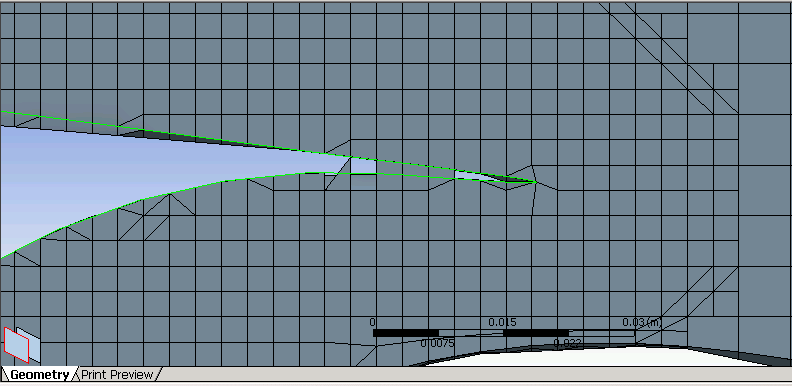
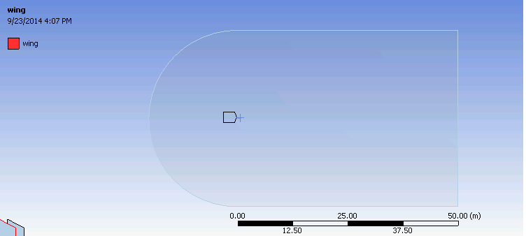
I have been trying to mesh a NACA 23012 airfoil with 25% slotted flap using cutcell assembly meshing. The overall geometry capture of the mesher is quite good, however, it seems to miss small "details" in the geometry. The Geometry was created in Solidworks and imported directly into workbench (Pic attached). The problem area highlighted in the picture has mesh elements "cutting-through" the lip. The narrow portion of the lip is approximately 5 cm long and the top and bottom surfaces are attached by the means of a sharp spline. A picture of the mesh in this region is also attached. Through the method of trial and error I've been trying to figure out why this is happening but am unsuccessful so far. Ive tried: -Lowering Min size and Proximity Min-Size -Apply hard face sizing -Increasing the relavance -Program controlled inflation (this generally ends badly since I only have 64 GB of RAM on the machine) -Messing with the feature angle. (this does reduce the problem to some extent) ...All to no Avail. I hope CFD-Online can help me figure out where the problem lies so that I can fix it. Without you guys and this site, getting through senior year of Aerospace Engineering is IMPOSSIBLE  Mesh Settings Relevance: 20 Size Function: Proximity & Curvature Relevance Centre, Smoothing: Fine,High Curvature Normal Angle: 90 Proximity size Function Sources: Faces & Edges Min Size: 3mm (Domain is a C Duct with a 20m radius and 50m wake region extruded out to 1 metre (pic attached) Proximity Min Size: 8mm Growth Rate: 1.2 - Min Edge length is found to be 0.540 m Face Sizing on the main airfoil is set to 3mm hard. No sizing on flap. Cut Cell Assembly mesh with feature capture by means of feature angle at 90 degrees. Absolute Tolerance for Tessellation refinement set to 0.00015m (5% of min size) Intersection feature creation is program controlled. Geometry  Mesh  Domain 
|
|
|
|

|
|
|
|
|
#2 |
|
New Member
Vasu
Join Date: Sep 2014
Posts: 2
Rep Power: 0  |
Lowering the Proximity min size along with global min size seems to have fixed the issue for now...

|
|
|
|

|
|
|
|
|
#3 |
|
Senior Member
Join Date: Mar 2014
Posts: 375
Rep Power: 13  |
clearly the cell size ware larger than the dimensions of the airfoil, i would rather have a tet mesh for an airfoil and inflation on the surface. this idea of using cut cell meshing for an airfoil doesn't look very nice to me
|
|
|
|

|
|
 |
|
|
 Similar Threads
|
||||
| Thread | Thread Starter | Forum | Replies | Last Post |
| how to set periodic boundary conditions | Ganesh | FLUENT | 15 | November 18, 2020 07:09 |
| [snappyHexMesh] problems generating clean mesh | Christian_tt | OpenFOAM Meshing & Mesh Conversion | 2 | June 20, 2019 06:39 |
| [ANSYS Meshing] Assembly inflation mesh failing for different geometry orientation | PedFr0 | ANSYS Meshing & Geometry | 0 | June 12, 2014 09:21 |
| fluent add additional zones for the mesh file | SSL | FLUENT | 2 | January 26, 2008 12:55 |
| unstructured vs. structured grids | Frank Muldoon | Main CFD Forum | 1 | January 5, 1999 11:09 |