 |
|
|
[Sponsors] | |||||
|
|
|
#21 |
|
Member
Join Date: Oct 2015
Posts: 47
Rep Power: 11  |
All the bodies are single parts, just like in the real turbocharger really. So I've got on each side the housing, cap, wheel, bearings, nuts etc, and the shaft connecting the two, going through the shaft housing between the compressor and turbine housings.
Is the removal of the shaft really going to have no impact on the solution? I'm supposed to simulate the heat transfers in the shaft housing in particular. But I think this might be a good solution to begin with. Thanks for your explanation on imprinting. So if I get this right: in activating the mesh display in my geometry scene, I should be able to tell the difference between before and after imprinting, if I look at the right places? So now, suppose I remove the shaft (and a few other parts like the nuts etc which shouldn't impact the solution that much) and get the wheels 'floating' in the housings. How do I proceed to create those control volumes you're telling me about? I'm not familiar with this operation. Once the control volume is created I have to extract the volume again right? And how do I get the wheels to rotate after that? I still have a million questions on CHT...  I'd be really grateful if you could detail me the few steps to get me started, I'd try them out tomorrow morning and get back to you.. Jambond |
|
|
|

|
|
|
|
|
#22 |
|
Senior Member
Join Date: Nov 2010
Location: USA
Posts: 1,232
Rep Power: 25  |
The removal of the shaft will have nearly no impact on the fluid solution, but you're correct that it will have a change on the solid side. I too think it's a good simplification to make to get you moving.
You're correct on looking at the imprint differences. You can create the control volumes in two ways: 1. Using simple shape parts. Right-clicking the parts folder will let you create simple shapes, of which you will probably want to use the cylinder. Position it around your wheel and that's all. 2. Using 3D-CAD. You can basically create a sketch plane in a coordinate system around the wheel. Draw out the outline of the volume you want and revolve. This is useful if other geometry makes using just a cylinder impossible. With this method the interface can be arbitrarily shaped. After that you should be able to select all of the parts and use the extract volume. You may need multiple for each of the rotating and non-rotating fluid regions. Then check the contacts folder and ensure that all of the contacts you need are present. To get the wheels to rotate (are you doing steady or transient?), you need to create a coordinate system for each wheel. Then create a motion (tools > motions) for each wheel. Under each region, you can specify a motion (physics values > motion specification). If you are doing steady (MRF), then set the reference frame to the proper wheel's reference frame. If transient (RBM), then you set the motion. Hopefully you can get through this, but my responses over the next week or so will be very limited. |
|
|
|

|
|
|
|
|
#23 |
|
Member
Join Date: Oct 2015
Posts: 47
Rep Power: 11  |
Thanks for the reply, I've tried a few of those things out.
I'm still struggling a bit with the control volumes: once everything has been sketched, repaired, imprinted just right, I get this same old error about the topological regions when trying to extract the volume. I ran a twin simulation with exactly the same parts (= deleting the shaft and all the tiny parts leaving just the wheels floating) but with no control volume and the extraction worked just fine. So my problem lies in the volume definition. I see several possible sources: - I positioned my sketch plane 'manually', in that I created a new plane parallel to the XY plane and then adjusted the coordinates until it got approximately in the middle of the wheel... Maybe that's not precise enough, do you see another way? - There's very little space between the wheel and the housing, and I'm guessing the control volume must intersect none of the two... I tried to be as accurate as possible when sketching but could the problem stem from there? - I chose 'Sheet' for the type of volume while creating the revolution of my curve. Should I have gone for 'Solid' instead? - I may have forgotten an essential step somewhere...? Basically I: imported the CAD, created parts, deleted a few ones, repaired the surface, filled the holes (and thus created new part surfaces), created a new sketch plane and sketched the outline of the wheel (left a tiny space between the wheel and the sketch line), revolved it, imprinted all parts together and then extracted the volume. Am I forgetting something? Also I'm not sure what you mean when talking about several volume extractions... I have to extract the volume between the housing and the control volume first; that will then be the air. And then another extraction between the control volume and the wheel, for it to rotate within the control volume? Or am I seeing this wrong? As for the motion (rotation), I browsed through the different menus and options and tried to get familiar with them but we'll back to it later once the extraction problem is solved. Thanks anyway for these first answers, I hope we can get a bit further until the end of the week. Jambond Last edited by Jambond; November 3, 2015 at 06:22. |
|
|
|

|
|
|
|
|
#24 |
|
Member
Join Date: Oct 2015
Posts: 47
Rep Power: 11  |
Hello hello!
So I've come a bit further I think, I thought I'd let you know where I'm at so you can catch up when you come back. Currently my CAD still has problems on the turbine side, I'm working on them. Right now I'm focusing on the compressor side which is fine. I managed to extract the volume properly removing just one little part and the shaft like you said. So I'm pretty happy with this and thanks for your help on it. Now, I'm working on this control volume thing. I drew the outline of the wheel (as close as possible to the wheel itself) on a manually created sketch plane and revolved choosing "solid" the solid mode. I thus created a new body under 3D CAD from which I created a new geometry part. I appears in the parts tree alright but I can only see the part when highlighted, otherwise it doesn't show on the geometry. Is this normal? I was finally able to extract the volume around this control volume. For this I had to delete and recreate my inlet/outlet surfaces (created in the surface repair module) because they ceased showing up when clicked... Does this normally happen on occasion? Anyway the extraction functioned and it looks okay but I'm not sure if it's entirely right: it's really hard to tell if it includes the control volume or not (it shouldn't) because of the flashy pink display... Any way to make sure of this? Assuming this is solved, I just have to do the same thing on the turbine side and my geometry is ready isn't it? Or am I forgetting something? I then gave the motion part another go; I basically followed this tutorial: http://www.cd-adapco.com/blog/dr-mes...alysis-vehicle ... and successfully completed all the steps. I can't really tell if it's enough for the wheels to rotate properly once the simulation is started but anyway I did what I was told to do  Have I forgotten something? What can I do next? Thanks for your help! Jambond Edit: I tried to generate a surface mesh just for kicks, but the surface remesher stopped and told me this: "Found and removed 2 duplicate face pairs Unable to remesh due to duplicate faces: 5 duplicate face pairs." What does this mean? Where does it come from? |
|
|
|

|
|
|
|
|
#25 |
|
Senior Member
Join Date: Nov 2010
Location: USA
Posts: 1,232
Rep Power: 25  |
If you can't highlight parts or seem to find them, it's extremely unlikely they've just disappeared. You will want to check two things:
1. That the representation of the scene/displayer is set correctly (right click any scene in blank space, and go to representation). Alternatively, every displayer in a scene also has an individual representation to set. If you set your representation to "volume mesh" and you are trying to see geometry that is not meshed, seemlingly nothing with show up. 2. You don't have the part/surfaces in a displayer If you suspect a surface has been deleted accidentally or by some other reason, you can right click on any parts surface and say statistics. If it says zero, there are no faces in that surface and it is indeed empty. The extract function can happen in a few different ways. The one I would suggest for now is to try setting the volume specification to automatic and choose ALL bodies instead of 'single'. This should give you two output parts, one non-rotating, one rotating. That tutorial is for setting up wall velocities, not rotations. You may need to set a wall velocity for any walls that are supposed to be rotating but are not in a rotating region; this is acceptable for 'simple' surfaces like the shaft, as it will cross the interface. However, for the actual rotating reference frame setup, that article references another one on setting up MRF, I'm assuming you should follow that. If you have a duplicate face issue, there is very likely a problem in your imprint someplace. The error message should point out a position in space where the problem is. I make some kind of part (like a sphere or something) that has a center near that point. That will show you the problem area. |
|
|
|

|
|
|
|
|
#26 |
|
Member
Join Date: Oct 2015
Posts: 47
Rep Power: 11  |
Thanks for the advice on the missing surfaces, they had a 0 in statistics indeed. Whenever this happens I just recreate them so it's not that big a deal, but it keeps happening every now and then without any reason...
I started over with the new geometry I received this week, and the duplicate faces error doesn't show anymore. I tried what you said with the extraction in auto mode, here's what I got:  And in the tree:  So there does seem to be one rotating part (the control volume) and one non rotating (the cap) but is it what you meant? I still find the extracted volume odd. Here's a screenshot:  One shouldn't be able to see the wheel right? Or maybe it's just because of the opacity... I don't know. I'm still not sure whether the extraction is right  In the end I re-ran a mesh generation and it stopped at this error:  What does this mean? One last question; I ran a diagnosis on my new geometry, and it's got no free edges and no non manifold vertices but there's about a hundred non manifold edges. I clicked on them and here they are:  They're basically the edges from the inlet/outlet surfaces I created... Do you know how to remove them? Or does it even matter? Thanks for your answers! I'll try and check out the MFR tutorial but it requires registration at CD Adapco and I can't get to log myself in... I asked the support, we'll see. |
|
|
|

|
|
|
|
|
#27 |
|
Senior Member
Join Date: Nov 2010
Location: USA
Posts: 1,232
Rep Power: 25  |
Perhaps I should try and make a mock-geometry to demonstrate what I'm saying if you can't let me take a look at yours; it's just a little tough to tell what's going on from a few images. It looks like it could be right, but it's hard to tell.
That error can mean several things, though; either a contact has some faces that are missing or you have a few collapsed faces or something of that nature. Does it happen before or after running the surface remesher? Those non-manifold edges are OK since they are your BCs and you are using extract volume. You can ignore them. |
|
|
|

|
|
|
|
|
#28 |
|
Member
Join Date: Oct 2015
Posts: 47
Rep Power: 11  |
I would say before, here's the (almost) full process:
 I don't see the surface remesher starting anywhere. I tried to locate patch 46866, and as implied in the report it seems to be shared by 3 boundaries: the cap (Deckel), the housing (Gehaeuse) and the extracted volume. I zoomed in on the corresponding area and here's what it looks like on the housing:  ... on the cap:  ... and on the extracted volume:  I get the feeling that in this particular area the housing should be round and it isn't (or not enough), and therefore collapses with the cap and the extract volume in between... Is there any way to solve this problem without editing the source geometry? I'm not able to do that myself and would like to avoid using ProE as much as possible (I'm not familiar with it). A mock geometry would be great... I asked my advisor again and he firmly refused for me to share the CAD  Edit: Since I figured the problem shown above was one of collapsed faces, I quickly edited the CAD and reduced the diameter of the inner part. That way there is no chance the cap and housing are in contact; even though it makes less sense in terms of design. Anyway I loaded this new model into a new simulation, extracted the volume and tried to mesh. This time the surface remesher did start; but I got a fatal error at the 'Improving quality' step. Here's the report:  It looks really bad... but I have no idea what it means! Seen this before? Thx! Last edited by Jambond; November 9, 2015 at 11:59. |
|
|
|

|
|
|
|
|
#29 |
|
Senior Member
Join Date: Nov 2010
Location: USA
Posts: 1,232
Rep Power: 25  |
It's hard to tell, but the problem you have looks like your imprint tolerance may be too high or low; it looks like some faces have been put on to wrong surfaces. What was the tolerance, and what's the size of that yellow ledge?
I'm trying to make a mock geometry in spare time. Your PK (Parasolid Kernel) error means there's something wrong with the CAD definition that the PK could not figure out. You can skip it by disabling CAD projection (under default controls of the mesh operation), but you will loose some definition in the CAD. |
|
|
|

|
|
|
|
|
#30 |
|
Member
Join Date: Oct 2015
Posts: 47
Rep Power: 11  |
I think the tolerance was 10^-4 m to begin with (default value).
Anyway I changed the value and it solved the problem, and enabled the surface remesher to launch. But it stopped at improving quality just like in my other simulation, with the same PK error. I unchecked CAD projection as you said, and got another error telling me that projection needed to be enabled in order to create aligned meshes. So I went and disabled "Create aligned meshes" as well. Is it okay? After that the surface remesher worked  It looked fairly ugly so I refined the mesh with a base size of 0.1m, a relative min size of 2.5% and a relative target size of 10%. Then I thought I'd go on and launch a volume mesh, but it immediately stopped, giving me this error:  I located the problem area by creating a small sphere like you said and it's at the interface between the turbine cap and the turbine housing:  So I figured maybe my imprint tolerance was not appropriate. I changed it to a smaller value (I think 0.00005 or so), tried to mesh again and I got another error:  Finally I tried a few other tolerance values, sticked to 10^-5 m and tried to mesh again. The surface meshing went alright, but the volume meshing gave me a whole new error:  I had a look at the report and it read the following:  What do you think I should change to fix this? |
|
|
|

|
|
|
|
|
#31 |
|
Senior Member
Join Date: Nov 2010
Location: USA
Posts: 1,232
Rep Power: 25  |
All of your errors seem to be around that point, what does the geometry pre and post imprint look like there?
|
|
|
|

|
|
|
|
|
#32 |
|
Member
Join Date: Oct 2015
Posts: 47
Rep Power: 11  |
I performed a cross section view using clip planes (another feature I didn't know about!) and zoomed in on one of the problem areas.
The issue seems to come up in several places of the geometry, basically wherever two parts (typically cap and housing) are in contact on a short cylindrical section. Here's before and after imprinting:   You can clearly tell the difference between the two, as you can witness those sharp triangles produced by the imprinting. Where does this come from? The merge angle parameter? The report was reading about face proximity and edge dihedral angle filters in manual repair... Do you know what they are and how to change them (if that makes any sense for my problem)? Last edited by Jambond; November 11, 2015 at 07:44. Reason: typo |
|
|
|

|
|
|
|
|
#33 |
|
Senior Member
Join Date: Nov 2010
Location: USA
Posts: 1,232
Rep Power: 25  |
You can change the reports in surface repair by clicking on manage thresholds; there you can generate your own metrics or manipulate the ones present.
The images you put here look like they aren't imprinted well in the second one. You can see some triangles matched, but a lot are overlapping. What is the distance between those two walls, and what is your imprinting tolerance? The imprinter imprints edges first, so it (might be counterintuitive) may be beneficial to loosen the tolerance if the edges aren't aligned, as it appears on the LHS of your image. |
|
|
|

|
|
|
|
|
#34 |
|
Member
Join Date: Oct 2015
Posts: 47
Rep Power: 11  |
I'm not sure what you mean by "the edges aren't aligned"... Which edges? The triangles'? Can you show me where on the picture where the problem is?
I can always try to loosen the tolerance and see what it looks like, I'll do that tomorrow. But I'd like to understand more precisely what's going on so I can tell if there's any improvement then  Thanks! |
|
|
|

|
|
|
|
|
#35 |
|
Member
Join Date: Oct 2015
Posts: 47
Rep Power: 11  |
Here's what I did today:
So first I had a look at the imprint for several tolerance values. I stuck with a merge angle of 0,523 rad (30°) for all of them. Here's the non imprinted view: 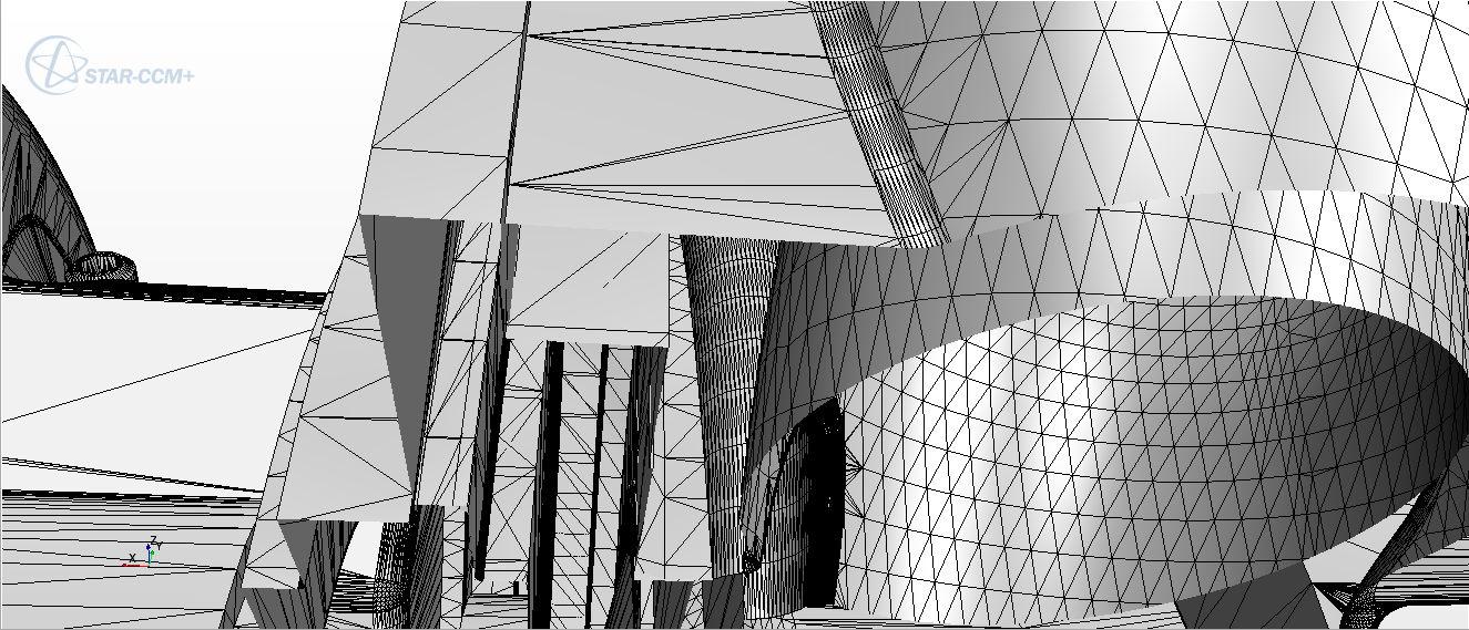 Tolerance = 0.0001: 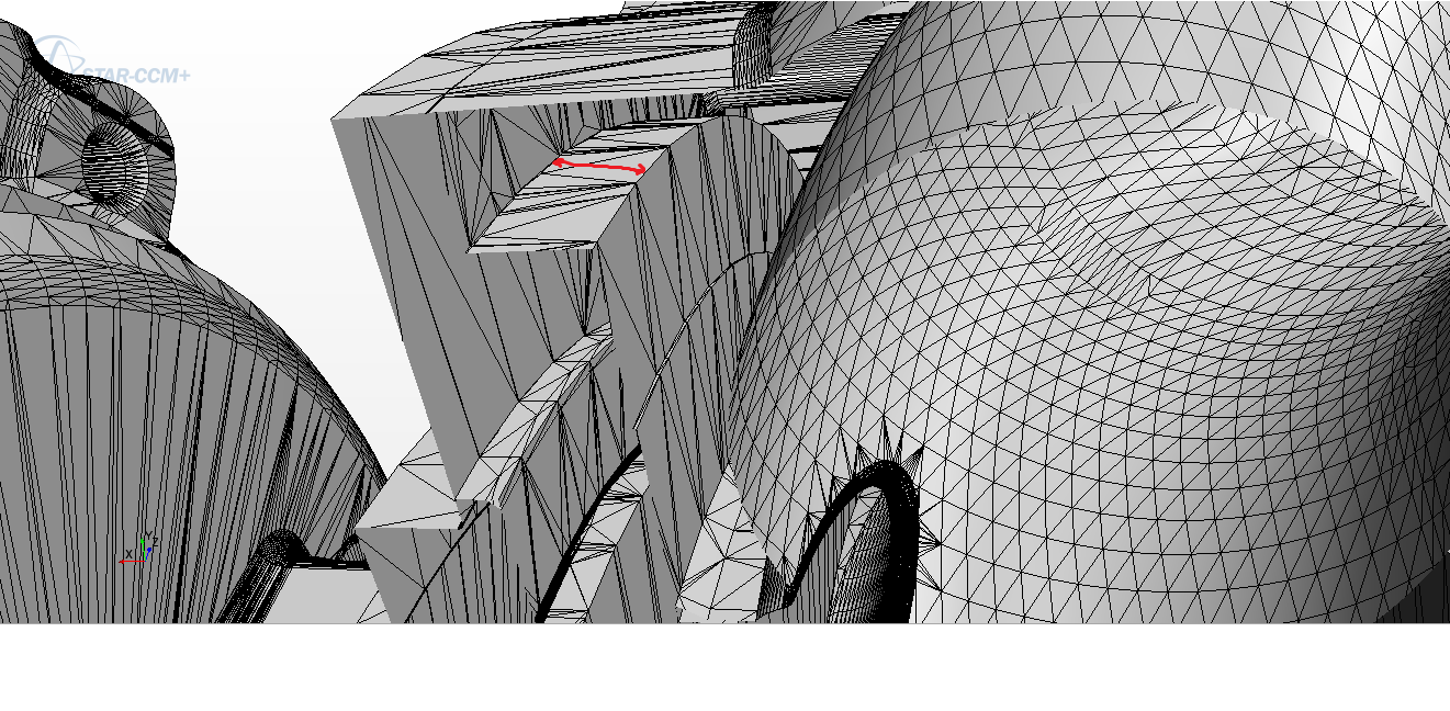 Note: the distance marked in red is approximately 3mm. Tolerance = 0.0003: 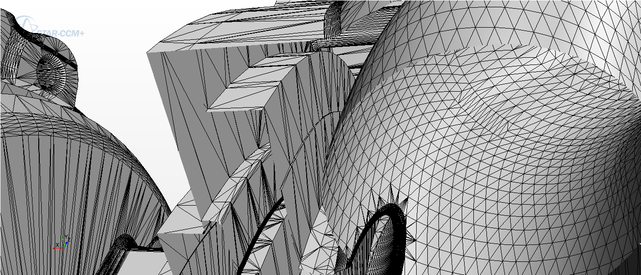 Tolerance = 0.0005: 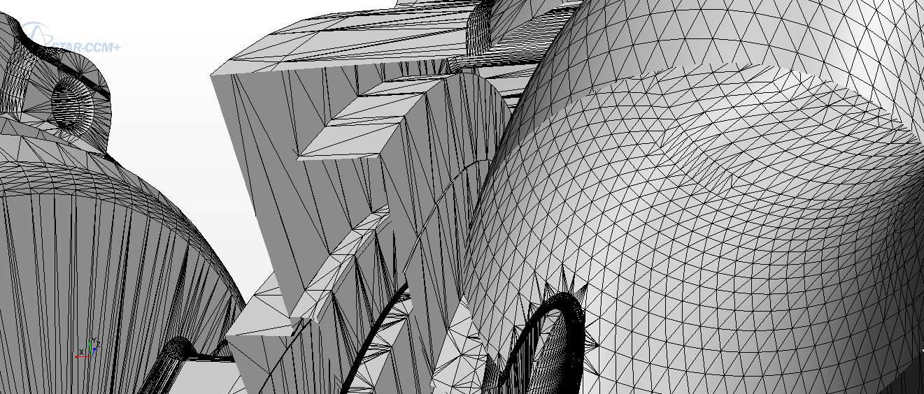 Tolerance = 0.001: 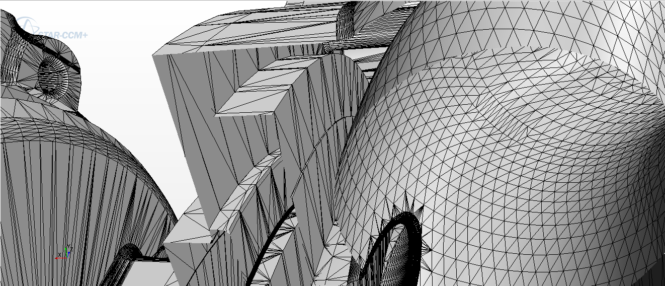 I then moved back to my model and try to mesh with the 0.0005m tolerance because it looked fine and took much less time that the 0.001. But it didn't manage to extract the volume. So I thought I'd loosen the tolerance to 0.01m and see what it'd say. It didn't even compute. I changed it to 0.001m; the imprinting took ages, and then the volume extraction failed as well as before. In the end the only power of 10 giving me a successful extract volume and surface mesh was 10^-4. So I tried out a few values around that one: 0.0001 : Volume mesh failed ("4 faces connected to the edge") 0.0002 : Extract volume didn't work 0.00025 : Surface mesh failed due to duplicate faces 0.00026 : Surface mesh failed due to duplicate faces 0.00027 : Volume mesh failed ("Connectivity error" and report about sharp dihedral angles like before) 0.00028 : Volume mesh failed, following error:  0.00029 : Volume mesh failed ("4 faces connected to the edge") 0.0003 : Volume mesh failed ("4 faces connected to the edge"), in another area as before. Here's what the imprint looks like there: 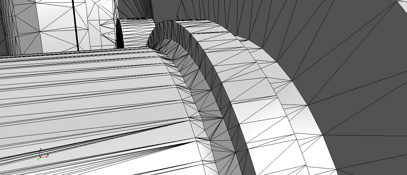 I can't even find a pattern in those errors... Maybe you will? Right now I have no idea which value to choose. It's either too high or too low to complete the surface mesh, and those in between don't work for the volume mesh. 
|
|
|
|

|
|
|
|
|
#36 |
|
Senior Member
Join Date: Nov 2010
Location: USA
Posts: 1,232
Rep Power: 25  |
All three of those first imprints looked just fine, I bet the problem you saw was elsewhere. If you want to find that free edge, just right-click the 'imprint' description and repair surface it. Then check for free edges and you'll see where the problem is.
|
|
|
|

|
|
|
|
|
#37 |
|
Member
Join Date: Oct 2015
Posts: 47
Rep Power: 11  |
The report was telling me that the part in question was the turbine housing, so I surface repaired it and it found no free edges...
 For other values of the imprint tolerance it kept pointing out issues in the turbine housing/cap area. The report was always mentioning these boundaries/regions, so I had a look at the interface between those two parts, and here's what it looks like: 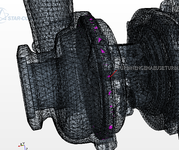 Not really what I expected, it should be a ribbon more or less, and not triangles here and there. It looked to me as if the turbine side was really faulty CAD wise, so I created a copy of my current simulation where I simply deleted the turbine, to see if the volume mesh worked on the compressor side. ... well it didn't, here's the error I keep getting while trying to volume mesh (surface remesher works fine):  (Note: "Verdichtergehaeuse" means compressor housing, so it has to do with the boundaries attached the this housing and the extract volume...) I've got this error before and I don't know what it means. Why would an odd number of faces be a problem? I keep seeing the boundaries and regions mentioned in the report and I don't really know what to do with them. When the problem comes from the CAD or the geometry part I know I can surface repair it or change the imprint values, but here it keeps mentioning the boundaries and interfaces, as if the regions weren't defined properly. Could this have something to do with the extract volume? Since it's not really a part... I still have to create a region for it, right? But maybe with some different settings? |
|
|
|

|
|
|
|
|
#38 |
|
Senior Member
Join Date: Nov 2010
Location: USA
Posts: 1,232
Rep Power: 25  |
Any particular edge in a surface must be attached to at least two faces, and any edge on an interface could be attached to as many as 4 but else only two still. If you have this error there's almost certainly something wrong with the imprint.
When the code tells you there's a free edge, you must look at the correct representation. If there's a free edge found during meshing but the geometry is clean, you need to look at the imprint output, and then if that's clean, the remesher output. How critical is it you use conformal interfaces here? I mean, can we get by with nonconformals? |
|
|
|

|
|
|
|
|
#39 |
|
Member
Join Date: Oct 2015
Posts: 47
Rep Power: 11  |
Thanks for your reply. So on those three topics:
1) I understand that the error comes from the imprint, but what I don't get is what I can precisely change to fix it. I only have two parameters, the tolerance and the angle. For my model without the turbine (where I'm getting this error about the odd number of faces), I tested several values and came to the conclusion that the tolerance must range between 0.00026 and 0.0003m for the surface remesher to work. Values above and below lead to errors either while extracting the volume or surface meshing. I wasn't very successful with the merge angle either... If the problem does lie in the imprint values then how can I change them cleverly? 2) My bad on the free edges, I misunderstood what you were saying. I surface repaired the part in 'imprint' mode and found the free edges: 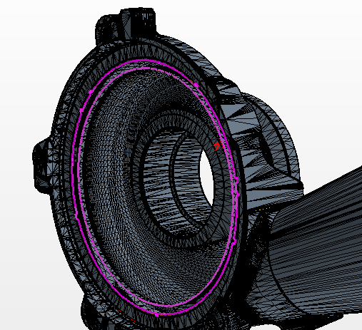 Actually the imprint basically deleted a surface, which created those 800+ free edges. It's pretty obvious on that close up:  So now that I found them, is it actually relevant to try and do something about it? I mean, shouldn't I just stick to another tolerance since this one gives me faulty results? Is there a way to 'fix' those free edges other than to change the imprint values? 3) I don't know how 'critical' it is. I haven't been able to get any results whatsoever up till now anyway so maybe it's better than nothing to begin with... However I read this article on the Steve portal: https://steve.cd-adapco.com/articles/en_US/FAQ/KH-4-101 Since I'm aiming at CHT, isn't it a bad idea to use non conformal interfaces? I'm not really familiar with them though so I'm not sure  Say we go non conformal, what do I have to modify on my model? I've never done this before... |
|
|
|

|
|
|
|
|
#40 |
|
Senior Member
Join Date: Nov 2010
Location: USA
Posts: 1,232
Rep Power: 25  |
Getting good imprint settings is a mix of luck with your CAD quality and trial-and-error. There isn't a lot of cleverness to it.
I seem dumb for asking this now, but I can't remember, did we try the CAD imprinter? You don't want to be repairing imprints after the imprinting - that is a world of hurt and pain. Going non-conformal may help in just getting results. You will, of course, get less accuracy, but getting experienced with the imprinter takes time and mentoring, which you just might not have. Meshing non-conformal is very easy. You've already demonstrated that you have clean parts pre-imprint. Change the imprint operation mode to non-conformal. Then change your mesh operation to enable the per-part meshing option and mesh. You should encounter no problems. |
|
|
|

|
|
 |
|
|
 Similar Threads
|
||||
| Thread | Thread Starter | Forum | Replies | Last Post |
| [Other] Problem with negative volume in CFX | TallesC | ANSYS Meshing & Geometry | 3 | February 4, 2013 12:44 |
| [GAMBIT] Gambit - Problem having shadow wall on volume | ejvikings | ANSYS Meshing & Geometry | 3 | March 23, 2012 02:30 |
| [blockMesh] BlockMesh FOAM warning | gaottino | OpenFOAM Meshing & Mesh Conversion | 7 | July 19, 2010 15:11 |
| Zero Volume Fraction in Free Surface Problem | marega | CFX | 1 | September 10, 2009 07:31 |
| [blockMesh] Axisymmetrical mesh | Rasmus Gjesing (Gjesing) | OpenFOAM Meshing & Mesh Conversion | 10 | April 2, 2007 15:00 |