 |
|
|
[Sponsors] | |||||
|
|
|
#1 |
|
Member
|
Hi,
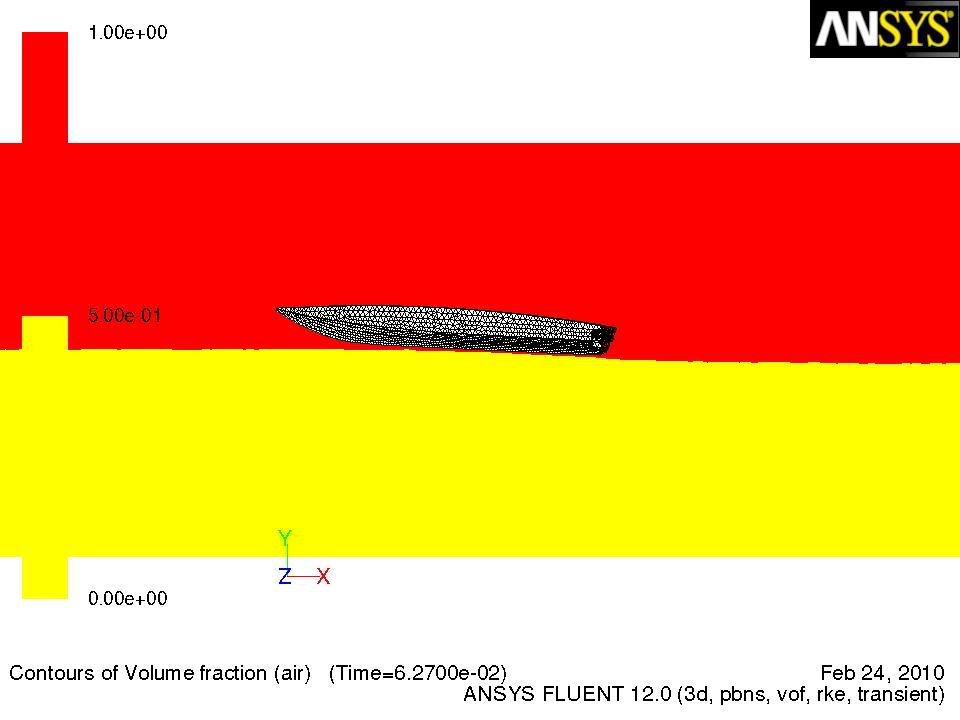
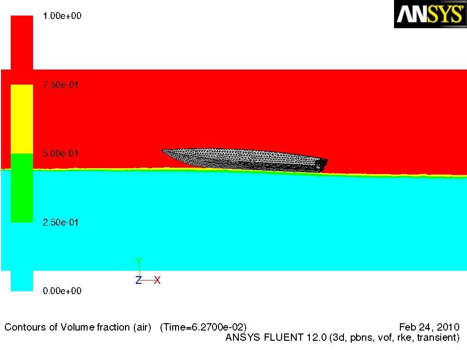
For my master thesis i have to study the flow around a speedboat. In gambit i've created a flow volume and substracted the hull from that volume. The BC's are: Pressure inlet, pressure outlet and moving walls, the hull is a fixed wal. The water flows from left to the right with a constant speed (30m/s). In Fluent i've followed the next steps: Steady Pressure based (Gravity enabled). VOF with Realizable k-epsilon. Material, phases, BC are defined the way it should be. (with specified density set to 0). Solution methods: Scheme: Simple, Pressure: Presto, Momentum: Power Law, Volume Fraction: Modified HRIC, rest: Power Law. Under-relaxation factors are decreased. Initialization on Inlet. start calculation. When i check the results i get the following solution. In a symmetry plane i want to see the contours of the 2 phases. When i plot them i get the following (with 2 phases):  There's no contact between the hull and the water. But the solution seems converged (Cl is constant and de residuals are converged till 10E-3) The wave after the hull looks correct but the forces (lift and drag) are to big. When i define 4 phases i get the following result:  This seems a lot better but i cant give a physical explanation to 4 phases.  So my question is: are my calculations wrong or is this 'visual' result just a part of postprocessing and i shouldn't pay to much attention to the colors? Thanks in advance! Vincent Last edited by vmeertens; February 28, 2010 at 17:03. |
|
|
|

|
|
|
|
|
#2 |
|
Member
|
I did a transient calculation after this, but it doesn't change anything to the results.
The initial water surface is set to y=0, so it should touch the hull in the middle. The hull is set under an angle of 2° (compared with pictures of the real boat) |
|
|
|

|
|
|
|
|
#3 |
|
Super Moderator
Maxime Perelli
Join Date: Mar 2009
Location: Switzerland
Posts: 3,297
Rep Power: 41  |
how did you initialize the vof (water)
Once the initialization is done, check the distribution of vof. Does your free surface agree with what you want?
__________________
In memory of my friend Hervé: CFD engineer & freerider  |
|
|
|

|
|
|
|
|
#4 |
|
Member
|
Hey,
The vof is patched as following: Adapt -> Region: dimensions of the volume of water. Initialize from inlet Patch -> Phase: water -> Volume fraction: 1 -> Hexadronr0 Patch -> X-Velocity -> Value: 30m/s -> Fluid At t = 0 the free water surface is as it should be. Now i'm doing the simulation with a better mesh thanks to mAx 
|
|
|
|

|
|
|
|
|
#5 |
|
New Member
Deepak Bansal
Join Date: Jul 2013
Posts: 9
Rep Power: 13  |
hey buddy i am also facing same problem in planing craft that air phase being formed on the bottom of the hull.................how did u solve this problem.................reply as soon as possible...............
|
|
|
|

|
|
 |
|
|
 Similar Threads
|
||||
| Thread | Thread Starter | Forum | Replies | Last Post |
| can melting model and vof model be used together? | wanghong | FLUENT | 3 | February 27, 2017 00:49 |
| A Problem with setting the time step in VOF model | Le | FLUENT | 2 | July 20, 2006 23:00 |
| free surface of VOF and melting model? | wanghong | FLUENT | 3 | March 13, 2006 10:57 |
| help needed for vof model | yan | FLUENT | 3 | December 16, 2005 02:17 |
| VOF Model | Arman Altincatal | FLUENT | 4 | April 12, 2002 17:26 |