 |
|
|
[Sponsors] | |||||
3D Flow Around A Stator Periodic Boundary Conditions Workbench |
 |
|
|
LinkBack | Thread Tools | Search this Thread | Display Modes |
|
|
|
#1 |
|
New Member
Euan Wheeler
Join Date: Mar 2014
Posts: 2
Rep Power: 0  |
I am having trouble applying periodic boundary conditions to my 3D problem in Workbench.
I have modelled and meshed one stator on the hub and I want this to have periodic boundary conditions on each side in order to characterise the flow. Does the geometry on each side of the mesh, the periodic interfaces, need to be identicle as I think this may be my problem? can anyone provide a step by step guide on how to apply this periodic/cyclic BC's. I managed to do this 2D with use of TUI, define>mesh-interfaces/make-periodic, having defined the two edges as interfaces in the mesher component of Workbench. The 3D geometry is a bit more problematic. Thanks. Euan |
|
|
|

|
|
|
|
|
#2 | |
|
New Member
Ontario
Join Date: Feb 2013
Posts: 4
Rep Power: 13  |
Quote:
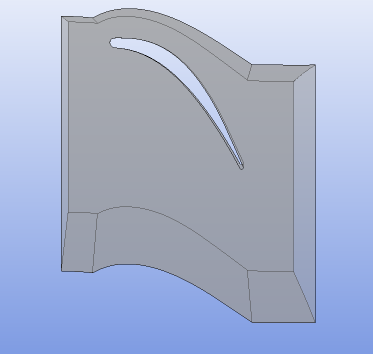
I am modelling a similar problem (stator (nozzle)blade of 1 Stage of a Low Pressure Turbine) however I am unable to figure out what should be the boundary conditions for my problem as I do not have anything before nozzles (no rotors). My geometry model as obtained from Tgrid looks like:  My doubt is that if I should be using identical domain geometry on pressure and suction side of the turbine. As, this domain has been automatically created by TGrid and I am not sure if it is correct. Also, Can anyone help me in setting up periodic Boundary Conditions for this problem. Thanks in Advance. |
||
|
|

|
||
 |
| Tags |
| fluent, periodic bc, stator, turbomachinery, workbench 14 |
|
|
 Similar Threads
|
||||
| Thread | Thread Starter | Forum | Replies | Last Post |
| Radiation interface | hinca | CFX | 15 | January 26, 2014 18:11 |
| Boundary conditions in Ansys workbench | revanth | ANSYS Meshing & Geometry | 9 | September 30, 2011 18:20 |
| 3-D Compressible Flow Boundary Conditions | Tyler | FLUENT | 4 | February 5, 2009 20:58 |
| boundary conditions for boundary layer flow | A. Al-zoubi | CFX | 0 | November 3, 2007 08:11 |
| Internal flow simulation boundary conditions | Kishore | FLUENT | 1 | July 10, 2007 12:42 |