Moved to http://lakeat.co.nf/
Enosh, a structured grid generator (III)
Posted February 28, 2014 at 16:21 by lakeat
Updated March 3, 2014 at 14:47 by lakeat (Clarification)
Updated March 3, 2014 at 14:47 by lakeat (Clarification)
Updates:
Finally, I got the boundary file output working. Now it is able to export to the OpenFOAM mesh format. But I still need to do some optimization (hopefully to make it back to log-complexity with hash tables, thanks to c++11). Currently it takes too much time to build an OpenFOAM mesh manually.
Also I have tested the code on a clean ubuntu 64 environment with virtualbox, it seems to me anyone who wants to use it needs vtk and qt installed. Using synaptic package manager, search vtk and install the vtk-dev, libqvtk-dev packages.
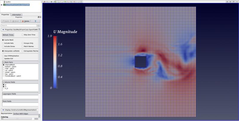
Here is a screenshot of a multi-block mesh simulation:

And the input mesh config file:
Finally, I got the boundary file output working. Now it is able to export to the OpenFOAM mesh format. But I still need to do some optimization (hopefully to make it back to log-complexity with hash tables, thanks to c++11). Currently it takes too much time to build an OpenFOAM mesh manually.
Also I have tested the code on a clean ubuntu 64 environment with virtualbox, it seems to me anyone who wants to use it needs vtk and qt installed. Using synaptic package manager, search vtk and install the vtk-dev, libqvtk-dev packages.
Here is a screenshot of a multi-block mesh simulation:
And the input mesh config file:
Code:
// ------------------------------------------------------------------------- //
//                                                                           //
//             ENOSH, a multi-block structured mesh generator                //
//                        Copyright 2014 Daniel Wei                          //
//                                                                           //
//                         Mesh Configuration File                           //
// ------------------------------------------------------------------------- //

// --------------------
// Description: A square cylinder mesh
// --------------------

// --------------------
// Geometry: NODES
// Format: NODE $NEWID $POINT
// --------------------
NODE 1  (-5, -5, 0);
NODE 2  (-0.5, -5, 0);
NODE 3  (0.5, -5, 0);
NODE 4  (5, -5, 0);
NODE 5  (-5, -0.5, 0);
NODE 6  (-0.5, -0.5, 0);
NODE 7  (0.5, -0.5, 0);
NODE 8  (5, -0.5, 0);
NODE 9  (-5, 0.5, 0);
NODE 10 (-0.5, 0.5, 0);
NODE 11 (0.5, 0.5, 0);
NODE 12 (5, 0.5, 0);
NODE 13 (-5, 5, 0);
NODE 14 (-0.5, 5, 0);
NODE 15 (0.5, 5, 0);
NODE 16 (5, 5, 0);

// --------------------
// Geometry: Edges and Their Dimensions
// Format: EDGE $NODE1ID-$NODE2ID [$DIMENSION] [$DELTA1] [$DELTA2] [$SMOOTHERBCTYPE] [$CAEBD]
// The order of node IDs is NOT important!
// Any bdName:bdType for the internal lines will be ignored
// --------------------
EDGE 1-2 50 0 0 0 bottom:symmetryPlane
EDGE 2-3 10 0 0 0 bottom:symmetryPlane
EDGE 3-4 50 0 0 0 bottom:symmetryPlane
EDGE 5-6 50 0 0 0 bdName:bdType
EDGE 6-7 10 0 0 0 cyl:wall
EDGE 7-8 50 0 0 0 bdName:bdType
EDGE 9-10 50 0 0 0 bdName:bdType
EDGE 10-11 10 0 0 0 cyl:wall
EDGE 11-12 50 0 0 0 bdName:bdType
EDGE 13-14 50 0 0 0 top:symmetryPlane
EDGE 14-15 10 0 0 0 top:symmetryPlane
EDGE 15-16 50 0 0 0 top:symmetryPlane
EDGE 1-5 50 0 0 0 inlet:patch
EDGE 5-9 10 0 0 0 inlet:patch
EDGE 9-13 50 0 0 0 inlet:patch
EDGE 2-6 50 0 0 0 bdName:bdType
EDGE 6-10 10 0 0 0 cyl:wall
EDGE 10-14 50 0 0 0 bdName:bdType
EDGE 3-7 50 0 0 0 bdName:bdType
EDGE 7-11 10 0 0 0 cyl:wall
EDGE 11-15 50 0 0 0 bdName:bdType
EDGE 4-8 50 0 0 0 outlet:patch
EDGE 8-12 10 0 0 0 outlet:patch
EDGE 12-16 50 0 0 0 outlet:patch


// --------------------
// Geometry: Blocks
// Format: BLOCK $NEWID ($IDLIST1 $IDLIST2 $IDLIST3 $IDLIST4)
// Note: The order of these IDLISTs IS important!
// --------------------
BLOCK 1 (1-2 2-6 6-5 5-1);
BLOCK 2 (2-3 3-7 7-6 6-2);
BLOCK 3 (3-4 4-8 8-7 7-3);
BLOCK 4 (5-6 6-10 10-9 9-5);
BLOCK 6 (7-8 8-12 12-11 11-7);
BLOCK 7 (9-10 10-14 14-13 13-9);
BLOCK 8 (10-11 11-15 15-14 14-10);
BLOCK 9 (11-12 12-16 16-15 15-11);
Total Comments 1
Comments
-
 I'm Happy to see this, actually i also trying to do the same in snappyhexmesh. I would be happy if i get the help in my problem......
Thanks in AdvancePosted July 16, 2022 at 04:49 by garva_mishra 


